Group 38 Fault Codes, Instrument Cluster Specifications
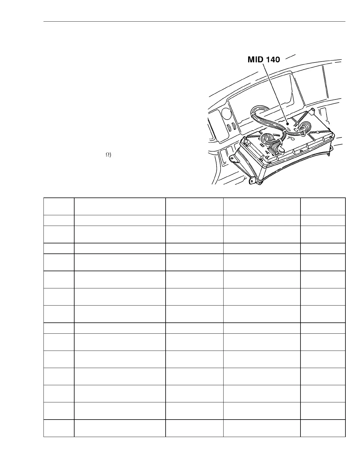
Connector B (30–pin Green) - breakout box connected between the in-
strument cluster (MID140) and cable harness
Requirements:
•
Breakout box 9998699 and adapter 9813194 con-
nected between the instrument cluster connector B
and the cable harness. Use extension cable
9990062 if needed.
•
Instrument cluster connected.
•
Ignition key in the drive position.
•
Engine switched off.
•
Measuring voltage using the multimeter.
Notes:
V = direct current voltage (V)
V
bat
= battery voltage
R = resistance in ohms (
)
W3005144
Pin Signal type Measurement
points
Nominal value Other
B1 Reference Ground (redundant) B1 - ground V ≈ 0V
B2 Application air pressure sensor,
analog input
B2 - ground V ≈ 0.5 - 5.0 V
B3 Fuel level sensor, analog input B3 - B1 V ≈ 0-5V
B4 Pyrometer sensor signal, negative
analog input
B4 - B5 V ≈ 5 - 32 mV
B5 Pyrometer sensor signal, positive
analog input
B5 - B4 V ≈ 5 - 32 mV
B6 Rear air suspension pressure
sensor, analog input
B6 - ground V ≈ 0.5 - 5.0 V
B7 Front air suspension pressure
sensor, analog input
B7 - ground V ≈ 0.5 - 5.0 V
B8 Not used
B9 Outside temperature sensor, ana-
log input
B9 - B1 V ≈ 0-5V
B10 Forward rear axle temperature
sensor, analog input
B10 - ground V ≈ 0-5V
B11 Rear rear axle temperature sen-
sor, analog input
B11 - ground V ≈ 0-5V
B12 Transmission oil temperature sen-
sor, analog input
B12-B1 V ≈ 0-5V
B13 Front brake air pressure gauge
sensor, analog input
B13 - ground V ≈ 0.5 - 5.0 V
B14 Rear brake air pressure gauge
sensor (analog input)
B14 - ground V ≈ 0.5 - 5.0 V
5
 Loading...