Do you have a question about the Volvo XC90 2014 and is the answer not in the manual?
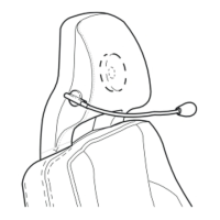
Extra caution required when working on vehicles with SRS/SIPS bag/IC systems to avoid injuries or system damage.
How to recognize vehicles equipped with SRS, SIPS bags, and IC through markings and features.
Recommendations for working on SRS, SIPS, and IC components, including wire handling and accessory fitting.
Location of the test terminal for the fuse in the cargo compartment auxiliary fuse box.
States that changes made after a specific date are not included in the manual.
How to order Electronic Wiring Diagrams (EWD) from the Technical Information Shop (TIS).
Lists the main groups and their corresponding topics within the manual.
Explains the symbols used for ignition switch positions.
Lists country codes used in the manual for market adaptations.
Provides definitions for abbreviations related to electrical and system components.
Lists color codes used for wires in the wiring diagrams.
Explains how component designations are structured into type number and serial number.
Lists type numbers and the corresponding component types they refer to.
Describes numbered branching points in wiring diagrams and where to find their lists.
Explains the role of connectors in bridging cable harnesses.
Refers to the section explaining fuses and relays.
Explains data communication networks like CAN, LIN, and MOST.
Refers to the section where abbreviations are explained.
Points to a section describing component appearance and location.
Explains the graphical symbols used in wiring diagrams.
Provides an overview of the electrical distribution diagram 1:2.
Provides an overview of the electrical distribution diagram 2:2.
Details fuses 1 through 5 in the engine compartment 11A fuse box.
Details fuses 1 through 12 in the engine compartment 11B fuse box.
Details fuses 13 through 15 in the engine compartment 11B fuse box.
Details fuses 16 through 21 in the engine compartment 11B fuse box.
Details fuses 1 through 8 in the passenger compartment 11C fuse box.
Details fuses 9 through 14 in the passenger compartment 11C fuse box.
Details fuses 1 and 2 in the passenger compartment 11O spare fuse holder.
Details fuses 1 through 7 in the cargo compartment 11E fuse box at the battery.
Details fuse 1 in the cargo compartment 11L Diesel fuse box.
Details fuses 6 through 12 in the cargo compartment 11O spare fuse holder.
Details fuses F1 through F10 for the Central Electronic Module (CEM).
Details fuses F11 through F34 for the Central Electronic Module (CEM).
Details fuses F1 through F19 for the Rear Electronic Module (REM).
Details fuses F20 through F38 for the Rear Electronic Module (REM).
Explains ignition switch positions and relay terminal designations.
Describes how relay positions are designated in diagrams.
Lists relays FMA1 through FST3 located in the engine compartment.
Lists relays R1 through R3 located in the cargo compartment.
Lists relays located in doors and other areas, and accessories.
Provides a visual overview of ground connection locations on the vehicle.
Details ground connection points 31/1 through 31/44 and associated components.
Details ground connection points 31/46 through 31/66 and associated components.
Details ground connection points 31/67 through 31/70 and associated components.
Details ground connection points 31/72 through 31/83 and associated components.
Details ground connection points 31/84 through 31/89 and associated components.
Details ground connection points 31/93 through 31/96 and associated components.
Details ground connection points 31/98 through 31/120 and associated components.
Illustrates the physical locations of various control modules within the vehicle.
Lists control modules with their unit designations and full names.
Wiring diagram for the Central Electronic Module (CEM), part 1 of 2.
Wiring diagram for the Central Electronic Module (CEM), part 2 of 2.
Wiring diagram for the Rear Electronic Module (REM), part 1 of 2.
Wiring diagram for the Rear Electronic Module (REM), part 2 of 2.
Wiring diagram for high-speed CAN data communication.
Wiring diagram for low-speed CAN data communication.
Wiring diagram for LIN data communication, part 1 of 2.
Wiring diagram for LIN data communication, part 2 of 2.
Wiring diagram for MOST data communication.
Wiring diagram for the cooling fan on 5-cylinder engines.
Wiring diagrams for cooling fans on 5-Cyl. Diesel and 6-Cyl. engines.
Wiring diagram for the cruise control system on 5-cylinder engines.
Wiring diagram for the cruise control system on Diesel and 6-cylinder engines.
Wiring diagram for the Diesel engine management system, part 1 of 3.
Wiring diagram for the Diesel engine management system, part 2 of 3.
Wiring diagram for the Diesel engine management system, part 3 of 3.
Wiring diagram for the 5-cylinder Turbo engine management system, part 1 of 2.
Wiring diagram for the 5-cylinder Turbo engine management system, part 2 of 2.
Wiring diagram for the 6-cylinder engine management system, part 1 of 2.
Wiring diagram for the 6-cylinder engine management system, part 2 of 2.
Wiring diagram for the emission control system on 5-cylinder Turbo engines.
Wiring diagram for the emission control system on 6-cylinder engines.
Wiring diagram illustrating the power supply system for the alternator and voltage regulator.
Wiring diagram for the starting system on 5-cylinder engines.
Wiring diagram for the starting system on Diesel and 6-cylinder engines.
Wiring diagrams for high/low beam, Dual Xenon, and Daytime Running Lights.
Wiring diagram for the Active Headlights (ABL) system.
Wiring diagram for the fog lights.
Wiring diagram for the brake lights.
Wiring diagram for the reversing lights.
Wiring diagram for the follow-me-home lighting system.
Wiring diagrams for running/parking lights, tail lights, and license plate lighting.
Wiring diagram for the interior lighting system.
Wiring diagram for the beam length adjustment system for headlights.
Wiring diagram for auxiliary lights.
Wiring diagram for the rain sensor system.
Wiring diagrams for direction indicators and hazard warning flashers.
Wiring diagram for the windshield wiper and washer system.
Wiring diagram for the high-pressure headlight washer system.
Wiring diagram for the rear window wiper and washer system.
Wiring diagram for the vehicle's horn system.
Wiring diagram for the immobilizer system.
Wiring diagram for the anti-theft alarm system.
Wiring diagram for the parking assistance system.
Wiring diagram for the alcohol lock system.
Wiring diagram for the Accessory Electronic Module (AEM), part 1 of 2.
Wiring diagram for the Accessory Electronic Module (AEM), part 2 of 2, detailing pin functions.
Wiring diagram for the vehicle's diagnostics system.
Wiring diagram for the 12V power outlet.
Wiring diagram for the 4/7 pin towbar/tow hitch cable harness.
Wiring diagram for the 7-pin towbar/tow hitch cable harness.
Wiring diagram for the 13-pin towbar/tow hitch cable harness.
Wiring diagram for the Accessory USB unit (AUU).
Wiring diagram for the seat belt reminder system.
Wiring diagram for the driver information module on 5-cylinder engines.
Wiring diagram for the driver information module on Diesel engines.
Wiring diagram for the driver information module on 6-cylinder engines.
Wiring diagram for the audio system with an external amplifier.
Wiring diagram for the audio system with an internal amplifier.
Wiring diagram for the portable navigation system.
Wiring diagram for the Road Traffic Information (RTI) system.
Wiring diagram for the satellite radio receiver and related components.
Wiring diagram for the rear seat entertainment system.
Wiring diagram for the Sensus infotainment system.
Wiring diagram for the parking camera system.
Wiring diagram showing the interaction between the parking camera and Accessory Electronic Module (AEM).
Wiring diagram for Bluetooth handsfree with an external amplifier.
Wiring diagram for Bluetooth handsfree with an internal amplifier.
Wiring diagram for Bluetooth handsfree with AEM (internal amplifier, LHD).
Wiring diagram for Bluetooth handsfree with AEM (internal amplifier, RHD).
Wiring diagram for Bluetooth handsfree with AEM (external amplifier, LHD).
Wiring diagram for Bluetooth handsfree with AEM (external amplifier, RHD).
Wiring diagram for the AW51 AWD automatic transmission.
Wiring diagram for the TF-80SC and TF-80SC AWD automatic transmissions.
Wiring diagram for the Geartronic AW51 AWD system.
Wiring diagram for the shift lock system in AW51 AWD and manual transmissions.
Wiring diagram for the Differential Electronic Module (DEM).
Wiring diagram for the brake control system.
Wiring diagram for the speed-dependent power steering system.
Wiring diagram for the central locking system.
Wiring diagram for the power windows.
Wiring diagram for the power sunroof system.
Wiring diagram for the power door mirrors.
Wiring diagram for the blind spot information system.
Wiring diagram for the heated door mirrors.
Wiring diagram for the heated rear window.
Wiring diagram for the power driver's seat.
Wiring diagram for the power passenger seat.
Wiring diagram for the heated seats system.
Wiring diagram for massage seats with ventilation features.
Wiring diagram for heated seats in the second row.
Wiring diagram for the rear climate control system.
Wiring diagram for the 5-cylinder climate control system, part 1 of 2.
Wiring diagram for the 5-cylinder climate control system, part 2 of 2.
Wiring diagram for climate control on 5-Cyl. Diesel and 6-Cyl. engines, part 1 of 2.
Wiring diagram for climate control on 5-Cyl. Diesel and 6-Cyl. engines, part 2 of 2.
Wiring diagram for the parking heater and auxiliary heater.
Wiring diagram for the parking heater with remote start functionality.
Wiring diagram showing the relay for the electric engine heater.
Wiring diagram for the refrigeration box located in the rear seat area.
Wiring diagram for the remote control garage opening system.
Wiring diagram for the Supplemental Restraint System (SRS), including airbag components.
Details for 4-pin gray and 14-pin gray connectors, including harness connections.
Details for 14-pin gray and 36-pin gray connectors and their harness connections.
Details for the 36-pin gray connector 54/3.1, covering passenger and engine compartment harnesses.
Details for 6-pin gray, 2-pin gray, and 6-pin gray connectors, covering various harnesses.
Details for 12-pin black connectors 54/10 and 54/11, covering front left/right door harnesses.
Details for 12-pin black and 6-pin orange connectors, including passenger and front right seat harnesses.
Details for 22-pin black and 5-pin green connectors, including roof and rain sensor harnesses.
Details for 12-pin black connectors 54/20 and 54/21, covering rear door harnesses.
Details for 12-pin black connectors 54/21 and 54/22, covering rear door and front left lamp harnesses.
Details for 10-pin black connectors 54/22 and 54/23, covering front left/right lamp harnesses.
Details for 10-pin black and 20-pin black connectors 54/23 and 54/24, covering front right/left seat harnesses.
Details for 20-pin black connectors 54/24 and 54/25, covering front left/right seat harnesses.
Details for the 20-pin black connector 54/25, covering front right seat and airbag harnesses.
Details for 3-pin gray, 4-pin gray, and 6-pin gray connectors, covering various harnesses.
Details for 6-pin gray and 2-pin black connectors, covering fuel tank/cargo and main fuses at battery harnesses.
Details for 2-pin black and 8-pin gray connectors, covering main fuses and airbag harnesses.
Details for 8-pin gray and 3-pin black connectors, covering airbag and brake pressure sensor harnesses.
Details for 3-pin black, 8-pin gray, and 4-pin yellow connectors, covering various harnesses.
Details for 2-pin black, 4-pin gray, and 6-pin gray connectors, covering infotainment and climate control systems.
Details for 12-pin gray, 1-pin blue, and 1-pin connectors, covering AUX, GPS, and GSM antenna harnesses.
Details for 12-pin gray and 1-pin connectors, covering RSE and battery plus harnesses.
Details for 6-pin gray connectors, covering PAM harnesses.
Details for 12-pin gray connectors, covering RSE tunnel and passenger compartment harnesses.
Details for 22-pin gray and 12-pin black connectors, covering RSE tunnel and TV receiver harnesses.
Lists branching points from 53/170 to 53/304 for 6-cylinder engines.
Lists branching points from 53/305 to 53/331.
Lists branching points from 53/332 to 53/394.
Lists branching points from 53/395 to 53/425.
Lists branching points from 53/430 to 53/452.
Lists branching points from 53/454 to 53/501.
Lists branching points from 53/503 to 53/526.
Lists branching points from 53/579 to 53/664.
Lists branching points from 53/733 to 53/3009.
Illustrates the routing of the engine harness for 5-Cyl. Turbo 2.5L engines.
Illustrates the routing of the engine harness for Gasoline 6-Cyl. engines.
Illustrates the routing of the engine harness for 5-Cyl. Diesel engines.
Illustrates the routing of the engine compartment harness for Left-Hand Drive vehicles.
Illustrates the routing of the engine compartment harness for Right-Hand Drive vehicles.
Illustrates the routing of the passenger compartment harness for Left-Hand Drive vehicles.
Illustrates the routing of the passenger compartment harness for Right-Hand Drive vehicles.
Illustrates the routing of the cargo compartment harness.
Illustrates the routing of the roof harness.
Illustrates the routing of the tailgate harness.
Illustrates the routing of harnesses for the front and rear doors.
Illustrates the routing of executive harnesses within the vehicle.
Illustrations of various components, including battery and relays (1/1 to 2/133).
Illustrations of various components, including relays and switches (2/138 to 3/4).
Illustrations of various switches and contacts (3/6 to 3/59).
Illustrations of various switches, motors, and lock units (3/60 to 3/77).
Illustrations of lock units, switches, and belt buckle contacts (3/78 to 3/95).
Illustrations of switches, modules, and selectors (3/106 to 3/156).
Illustrations of various switches, sensors, and boxes (3/157 to 3/320).
Illustrations of various modules, including CPM, SRS, BCM, TCM, and ECM (4/7 to 4/46).
Illustrations of various modules, including PSM, CEM, REM, UEM, SAS, and DEM (4/52 to 4/82).
Illustrations of control modules, trailer module, headlamp module, and USB unit (4/83 to 4/131).
Illustrations of seat motors, sunroof motor, starter motor, and massage seat modules (4/133 to 6/25).
Illustrations of ACM, fans, wiper motors, fuel pumps, and headlight adjustment motors (6/26 to 6/44).
Illustrations of damper motors, power window motors, and rearview mirrors (6/48 to 6/69).
Illustrations of steering valves, coolant pumps, climate control modules, and motors (6/71 to 6/104).
Illustrations of vacuum pumps, washer motors, throttle units, and seat ventilation fans (6/114 to 6/151).
Illustrations of seat fans, massage seat pumps, fluid sensors, and interior/exterior sensors (6/153 to 7/12).
Illustrations of oxygen sensors, knock sensors, impulse sensors, and ABS sensors (7/15 to 7/31).
Illustrations of ABS sensors, oil sensors, evaporator temperature sensors, and pedal sensors (7/32 to 7/62).
Illustrations of coolant sensors, fluid temperature sensors, pressure sensors, and OWS (7/73 to 7/103).
Illustrations of heated oxygen sensors, outside temperature sensors, impact sensors, and angle sensors (7/104 to 7/122).
Illustrations of clutch sensors, brake sensors, fuel sensors, and rain sensors (7/123 to 7/156).
Illustrations of mass movement sensors, air quality sensors, fuel rail sensors, and camshaft position sensors (7/158 to 7/173).
Illustrations of camshaft position sensors, differential pressure sensors, OWS, impact sensors, and climate control clutches (7/173 to 8/3).
Illustrations of injectors, turbocharger control valves, and airbag igniters (8/6-10 to 8/33).
Illustrations of belt tensioner igniters, shift lock solenoids, and transmission solenoids (8/34 to 8/40).
Illustrations of pressure solenoids, activation units, airbag igniters, and solenoids (8/41 to 8/66).
Illustrations of igniters, throttle solenoids, shift solenoids, and belt tensioner igniters (8/67 to 8/94).
Illustrations of belt tensioner igniters, fuel pressure valves, EGR valves, and airbag igniters (8/95 to 8/125).
Illustrations of solenoid cam profiles, pressure solenoids, and seat heating modules (8/126 to 9/13).
Illustrations of seat control modules, heating elements, and auxiliary heaters (9/14 to 9/33).
Illustrations of rearview mirrors, lamp housings, and fog lights (9/34 to 10/14).
Illustrations of direction indicators, lamp housings, and brake lights (10/15 to 10/47).
Illustrations of reversing lights, brake lights, high beams, and auxiliary lights (10/48 to 10/68).
Illustrations of auxiliary lights, low beams, side running lights, and vanity mirrors (10/69 to 10/149).
Illustrations of rear reading lights, lighting switches, fuse boxes, and diesel fuses (10/150 to 11L/1).
Illustrations of spare fuses, distribution boxes, and audio/speaker modules (11O/1 to 16/16).
Illustrations of speakers, siren modules, TV receivers, and navigation systems (16/26 to 16/56).
Illustrations of speakers, phone modules, GPS antennas, and microphones (16/57 to 16/77).
Illustrations of screens, control modules, audio modules, and microphones (16/81A to 16/127).
Illustrations of radio receivers, phone modules, data link connectors, and tow hitch cable harnesses (16/145 to 17/38).
Illustrations of tow hitch connectors, contact reels, spark plugs, glow plugs, and camera modules (17/39 to 27/3).
Illustrations of camera modules and various ground connection points (27/4 to 31/47).
Illustrations of ground connections at various locations, including rear seat risers and engine coils (31/48 to 31/88).
Illustrations of ground connections for engine coils, strut towers, windshield, and front member (31/88 to 31/120).
Illustrations of various connectors (54/1 to 54/12).
Illustrations of various connectors (54/13 to 54/34).
Illustrations of various connectors (54/35 to 54/55).
Illustrations of various connectors (54/56 to 54/139).
Illustrations of connectors (54/140 to 54/1403) and connecting rail A1.
| Brand | Volvo |
|---|---|
| Model | XC90 2014 |
| Category | Automobile |
| Language | English |