*911031-00*
911031-00
© Allegion 2021
Printed in U.S.A.
911031-00 Rev. 04/21-e
General Information
The Von Duprin DE5300 is designed for controlled egress applications when used in conjunction with a magnetic lock. It meets both life
safety and security needs, as well as the requirements of NFPA101 for “Special Locking Arrangement” and IBC “Special Egress-Control
Devices”. All control inputs, auxiliary locking, local alarm and remote signaling outputs are self-contained in the DE5300 assembly.
Numerous eld congurable options allow the device to be customized for the specic code or application requirements. The standard
DE5300 sounds an alarm and keeps the door secured for 15 seconds following an exit attempt with immediate release upon re.
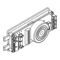
Parts Included
Module
Field Wiring Cable
Device Wiring Cable
Faceplate
#6-32 X 1/4” Mounting Bracket Screws (2)#6-32 X 3/8” Faceplate Screws (4)
Key SwitchMounting BracketControl Box
PUSH UNTIL ALARM SOUNDS
DOOR CAN BE OPENED
IN 15 SECONDS
Door Sign
Table of Contents
Basic Features........................................................................... 2
Installation Components ............................................................ 3
Electrical Specications ............................................................. 4
Typical Wiring Diagrams ............................................................ 4
Single Door ............................................................................ 4
Double Door .......................................................................... 5
Electrical Trim ........................................................................ 7
Retrot Wiring.............................................................................7
Installation ................................................................................. 8
Basic Functional Test ............................................................... 11
Module Setup .......................................................................... 11
Onboard Switch Settings Table ............................................... 12
Advanced Function Test .......................................................... 13
Onboard Indicators .................................................................. 14
Troubleshooting ....................................................................... 15
WARNING
• Do not exceed rated specications.
• The DE5300 must be installed in accordance with these instructions by a qualied electrician.
• Wiring and applications must be in accordance with all local codes and regulations.
Wiring and Conguration
DE5300 Delayed
Egress System
Installation Instructions
Customer Service
1-877-671-7011 www.allegion.com/us