16
FOR INSTALLERS AND PROFESSIONALS
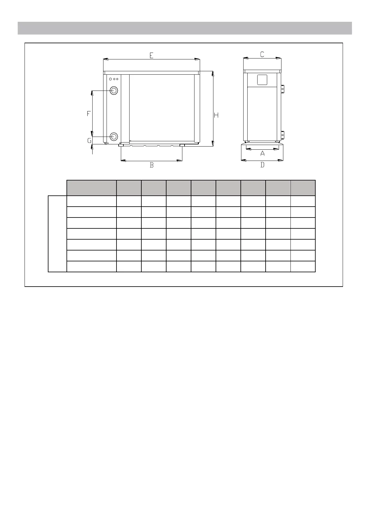
UNIT=MM A B C D E F G H
Model
VPROPLUS 11
402 539 389 432 910 300 73 660
VPROPLUS 14
402 574 389 432 945 340 73 660
VPROPLUS 18
402 674 389 432 1045 380 73 660
VPROPLUS 21
402 824 389 432 1195 470 73 760
VPROPLUS 26
511 700 498 536 1072 550 73 956
VPROPLUS 32
511 891 498 536 1264 570 73 956
VPROPLUS 40T
511 991 498 536 1364 670 73 956
※ Above data is subject to modication without notice.
2.2.2. Heat pump installation.
➢ The frame must be xed by bolts (M10) to concrete foundation or brackets. The concrete
foundation must be solid; the bracket must be strong enough and anti-rust treated;
➢ The heat pump needs a water pump (Supplied by the user). The recommended pump
specication-ux: refer to Technical Parameter, Max. lift ≥10m
➢ When the heat pump is running, there will be condensation water discharged from the
bottom, please pay attention to it. Please insert the drainage tube (accessory) into the
hole and clip it well, then connect a pipe to drain off the condensation water.
2.2.3. Wiring and protecting devices and cable specication
➢ Connect to appropriate power supply, the voltage should comply with the rated voltage
of the products.
➢ Well earth the heat pump.
➢ Wiring must be connected by a professional technician according to the circuit diagram.
➢ Set breaker or fuse according to the local code (leakage operating current ≤ 30mA).
➢ The layout of power cable and signal cable should be orderly and not affecting each
other. Considering the environmental conditions (ambient temperature, direct sunlight,
rain, grid voltage, cable length, etc.), the cross-sectional area of the cable can be
appropriately increased.
 Loading...