DESCRIPTION
An all in one system for autonomous control of heat pumps in line with the
filtration system.This unit permits the heat pump to run outside of filtration
hours set by sanitation timers allowing for full automatic heat demand.
OPERATION
The VortexLink is designed to switch a 240Vac pump rated to 10 Amps 2400
watts from the switch inputs. This unit is designed to be connected to a
chlorinator and the outputs from heat pumps.VortexLink is fitted with an LCD
screen which displays whether the pump is on and whether the chlorinator or
heat pump is demanding the pump to be operating.
HEAT DEMAND
A heating device, whatever it is, is designed to heat the pool water only when
the water circulates. Most of the time, a pool is filtered between 6 and 8 hours
a day. But such a time can’t be sufficient sometimes to maintain the water
at the desired temperature, depending on the seasons. This is the reason
why the heat pump is equipped with the “sample” function that will manage
the temperature of the pool. Every hour (times vary depending on the heat
pump model) the filtration pump is started for 5 minutes. If after 5 minutes,
the temperature of the water is above the required temperature, the filtration
turns off for one more hour. Otherwise, the filtration and the heat pump are
going to keep on operating until the desired temperature is reached.
INSTALLATION INSTRUCTIONS
Mounting
Find a suitable location to mount the VortexLink box. Ideally, as with all pool
equipment, it should be installed out of direct weather and no closer than 3m
from the water’s edge and a minimum 600mm above ground. Fix the mounting
bracket to a solid structure and slide the VortexLink on, keeping in mind that the
power cable is 1.8m long and should be plugged directly into a general power
outlet, not into an extension lead.
Pump
The filtration pump plugs into the 240V outlet beneath the VortexLink.
Heating Demand
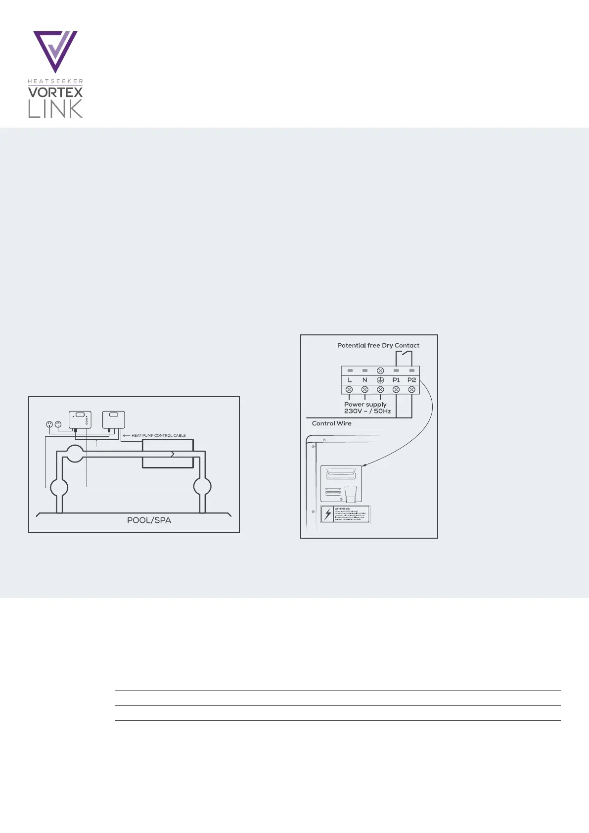
Connect the heat pump control cable from the VortexLink to the heat pump,
refer to the heat pump manufacturer’s instructions and the below diagram
for the appropriate connection and note that damage caused by incorrect
connections will void warranties.
WARRANTY
This range of product is covered by a limited 2 year warranty against component failure or faulty workmanship from the date of installation.
Faulty units should be returned in the first instance to the dealer from which the unit was purchased.
Damage to the unit due to misuse, power surges, lightning strikes or installation that is not in accordance with the manufacturer’s instruction may void the warranty.
Warranty does not include on-site labour or travel costs to or from installation site.
Customer Record. (To be retained by the customer)
Dealer/Installer Name
Serial Number
Date Installed
OPERATION & INSTALLATION
INSTRUCTIONS
CHLORINATOR
CELL
CHLORINATOR
NO VALINK
FILTRATION PUMP
FILTER
HEATPUMP
PUMP
SWITCHINGLEAD
PLUGINTO
240 GPO
31
 Loading...