CAUTION!
The chart obtains only for metallic housings.
For nylon housings the VOSS V-thread
has to be used.
Screw-in thread Nominal size Fir-tree for tubes
NS O.D. x wall thickness
M 16 x 1.5 8 6 x 1
8 x 1/9 x 1.5
10 x 1,25
10 x 1/11 x 1.5
12 x 1.5
M 22 x 1.5 12 6 x 1
8 x 1/9 x 1.5
10 x 1.25
10 x 1/11 x 1.5
12 x 1.5/14 x 2.5
12,5 x 1.25/14 x 2
16 x 2
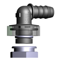
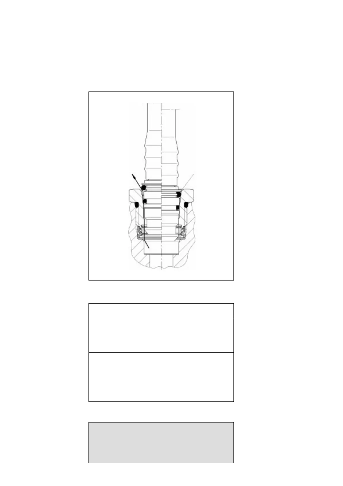
VOSS quick connect system 232, functional diagram
Retention of the plug in the
first snap-in stage thus solves
the safety problem of faulty
insertion, leading to sudden
failure of the connection and
subsequent breakdown of the
entire system. Compensation
for the minor leakage is
topped up by the compressor.
3.4 Product range
The VOSS quick connect
system is available in nominal
sizes 8 and 12.
Please refer to the table below
for possible combinations of
plug size and nylon tubing
dimensions.
The entire range of parts and
accessories for the VOSS
quick connect system 232 is
contained in catalogue 232.
3.3 Functional description
The coupling element forms
the connection to the compo-
nent. Connection is made by
screwing the coupling element
into an appropriate port.
Suitable ports are the industri-
ally standard moulded port for
the VOSS quick connect sys-
tem 230 and special port
shapes agreed with VOSS for
the application in question.
On request, we will be
pleased to supply design
specifications for the appropri-
ate port.
The connection between a
nylon tube and a component
is made by sliding the plug
into the coupling element.
When this is done the plug is
kept in place by a two-stage
retaining element which, once
it has reached its second
snap-in location, is automati-
cally shifted from the push-in
to the locking position by
means of axial compression
and the pressure of the com-
pressed air.
Should the second snap-in
stage not be reached due to
insufficient insertion force or
other unfavourable circum-
stances, the plug is safe from
disconnection as soon as the
retaining element has snap-
ped into the first stage.
It is possible to push the
retaining element into this first
snap-in stage by applying very
little force. In this retention
position, the connection has
an intended leakage path.
Incomplete connections may
be noticed by an acoustic
warning signal and a drop in
pressure.
4
Possible combinations
of thread size, nominal size and tube dimensions
First snap-in
stage
Second snap-in
stage
Axial
compression
Acoustic warning
signal through
leakage path
 Loading...