- 3 -
Configuration of Connections:
Colour Connection No. Tank Display Function recommended Cable Cross-Section
white 5 = Tank + (Plus) + Operating Voltage, from Display Unit Connection 5 0.5 - 1 mm²
green
4 = Tank Signal Measuring Signal to Display Unit Connection 4, 0…2.2 V 0.5 - 1 mm²
brown
1 = Battery - - Operating Voltage (common, minus) or Body Ground, 1 0.5 - 1 mm²
The tank electrode K is protected against any kind of reverse battery. It is recommendable to use connection cables of
different colours to avoid malfunctions due to mixed up connections.
As soon as the display unit has been installed according to the operating manual, the battery can be connected.
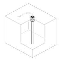
Start-up and Adjustment:
The adjuster at the upper side of the tank electrode is used to adjust the tank height to 100 % "FULL" at the display:
Insert a folding rule into the mounting hole of the tank to measure the exact tank depth (inside width), and set the adjuster
for the "water depth" to this value. The adjustment procedure is completed.
The functions of the display can now be simulated with several water levels in the tank (or in a bucket being filled with
water) or by withdrawing the tank electrode out of the full tank (or bucket).
Fine adjustment of the set water depth can be corrected or changed at any time with full tank.
Final Installation:
The delivered packing washer is placed between tank and casing flange. Screw the tank transmitter in place using the
coupling ring.
In case of underfloor installation of the tank, the adjuster must be protected with a permanently elastic sealant against
aggressive environmental influences (de-icing salt etc.).
Tips and Tricks:
No reaction of display:
a. Cable 4= Tank Signal Withdraw connector by way of trial and direct it to connection "5":
The display should increase to 100 % ! Otherwise:
b. Battery connection or fuse defective check!
c. Cable 5 = Tank Plus interrupted check!
d. Cable 4 = Tank Signal: Short-circuit to ground check!
Constant display of 100 % on the display unit:
a. Cable 4 = Tank Signal Withdraw it and direct it to ground: Display must be empty!
b. Cable 1 = Battery Minus / Ground is interrupted or does not have any contact due to paint residues at the bodycheck!
c. The insulated stick probe is contacting water: The silicone cap is leaky or dropped-off, the plastic pipe is damaged
check!
Indication Errors:
a. Intense soiling and furring of the insulated stick probe by stuck solids in the sewage water tank and feces tank
Rinse tank (no seawater), clean it if required !
 Loading...