EasyManua.ls Logo

Votronic VBCS 30/20/250 Triple - User Manual

Votronic VBCS 30/20/250 Triple
20 pages
Print Icon
To Next Page IconTo Next Page
Loading...
Mounting Instructions and Operating Manual for Unit Combination of
Mains Charger, Charging Converter and MPP Solar Controller including Battery Trainer
VBCS 30/20/250 Triple Converter VCC 12 V-12 V/30 A, AC Mains 12 V/20 A, MPP Solar 250 Wp No. 3241
VBCS 45/30/350 Triple Converter VCC 12 V-12 V/45 A, AC Mains 12 V/30 A, MPP Solar 350 Wp No. 3243
VBCS 60/40/430 Triple Converter VCC 12 V-12 V/60 A, AC Mains 12 V/40 A, MPP Solar 430 Wp No. 3245
All-automatic battery charger with 3 charging sources for optimum battery charging during
mains operation and solar operation, designed for motor homes and intervention vehicles.
Please completely read this operating and installation manual thoroughly prior to connection and
start-up, in particular "Safety Regulations and Appropriate Application", s. page 18.
VOTRONIC chargers of series "VBCS Triple" excel by their compact design, low weight (high-frequency switching power
supply, Switch Mode Technology), as well as the intelligent microprocessor charging control with characteristic lines of
charging „IU1oU2oU3“ and dynamic charging time calculation.
8 charging programs stored in the memory for Lead-Acid, Gel and AGM, as well as advanced Lithium LiFePO4 Batteries,
ensure unattended, quick and careful full charging from any charging state with subsequent trickle charging and maintenance
of the battery and simultaneous supply of the connected consumers 12 V during the entire charging process. Consumed
energy will be compensated immediately.
Mains Operation, during standstill operation at the external socket of the mains supply:
The full charging capacity in the universal wide range from 110 V AC - 230 V AC without any switching is available
worldwide, even in case of large deviations in the power supply (low voltage/overvoltage, sine curve, frequency).
Efficient charging of the board battery and supply of the 12 V consumers via mains.
Auxiliary charging 12 V/4-5 A for support charging and trickle charging of the vehicle's (lead) starter battery in case of
extended standstill periods.
Due to the long-term characteristic lines of charging, the unit may be connected continuously to the mains (such as for
standstill periods or winter breaks).
Charging Converter, "B2B" Operation, mobile operation from dynamo and starter battery (Battery to Battery):
The efficient charging converter (booster) allows full charging of the board battery during driving.
It increases/reduces the voltage to the level, which is required for precise charging of the board battery with the
optimum characteristic line of charging.
Cable losses and considerable voltage fluctuations of the dynamo, known from Euro 6 vehicles, are completely
compensated.
The simultaneously supplied 12 V consumers are protected against overvoltage and voltage fluctuations.
Solar Operation, "MPP" (Maximum-Power-Point):
Controllers according to the MPP technology are continuously and automatically calculating the maximum power yield
(MPP) of the solar modules several times per second. This surplus of charging current of 10 % to 30 % ensures short
charging times and the best possible power yield of the solar system.
Auxiliary charging for support charging and trickle charging of the vehicle's starter battery in case of extended standstill
periods.
Terminal "AES", for automatic commutation of refrigerators with "AES" (Automatic Energy Selector, Electrolux /
Dometic) from gas operation to 12 V operation in case of excess solar power.
Pulser Operation, training for the board battery during the charging breaks, if a charging source is not existing:
The battery training protects the unused (lead) battery during the winter break, seasonal operation or extended standstill
periods from premature ageing and failure due to sulphation.
Further Characteristics of the Unit:
The charging voltage being free from peaks is controlled in such a way, that overcharging of the batteries is excluded.
All-automatic Continuous Operation: The charger may be connected continuously to the batteries, thus keeping the full
charge. If the charging source is missing (power failure, engine stop, night), the batteries will not be discharged.
Parallel and Floating Operation: In case of simultaneous consumption, charging of the battery is continued or trickle
charging is effected. Calculation and control of the adaptation of the charging times is effected automatically by the
charger.
Question and Answer IconNeed help?

Do you have a question about the Votronic VBCS 30/20/250 Triple and is the answer not in the manual?

Summary

Installation of the Unit

Unit Connection

Describes how to connect the unit's power and control cables.

Unit Settings

Details how to configure battery type and other settings via switches.

Connection of the 9-pole Terminal Strip (Sensor Inputs, Terminals)

TT: Measuring input for the temperature sensor of the supply battery Board I

Connects the temperature sensor for battery monitoring.

Ss- and Ss+: Measuring inputs for accurate battery voltage, cables voltage sensor Sense:

Measures battery voltage to control charging voltage precisely.

TR - OK: Terminal for High-current Bypass Relay TR or Pilot Lamp OK (Option):

Terminal for bypass relay control or status indication.

+86: Terminal Engine Immobilizer of the Vehicle (Option):

Prevents engine start when connected to mains.

AES: Signal output for refrigerators with Automatic Energy Selector (option):

Outputs a signal to switch refrigerators to 12V operation.

Battery Temperature Sensor

Lead-Acid, Gel, AGM Batteries

Details installation and function for lead-acid type batteries.

LiFePO4 Batteries:

Details installation and function for LiFePO4 batteries.

Unit Settings

How to Set the battery type Board I (Design, Technology):

Explains how to select the battery type using slide switches.

Further Settings and Functions, 8 Slide Switches

Table 2: How to set Cap. Battery Size (Capacity, Ah) Board I:

Guide for setting the battery capacity using slide switches.

Activation of the Battery pulser (only possible with lead batteries):

Explains how to activate the battery pulser for lead-acid batteries.

How to activate the charging lock input Sw (only active with LiFePO4 batteries):

Describes how the BMS can lock charging for LiFePO4 batteries.

5.) A B:

Describes the function of switch A/B.

6.) TR OK:

Determines the function of the "OK TR" terminal.

7.) V D+:

Describes the function of the "V D+" switch.

8.) Limit II max:

Limits the maximum current consumption during B2B operation.

Operation

Push-button at the Unit Front AC Power Limit and AC Power Off:

Explains the functions of the front panel power limit and off buttons.

Option: Remote Controls and Displays (Tip Jack Display)

Describes how to use remote displays for monitoring and control.

Pilot Lamps

Battery Full (Battery Board I fully charged, green):

Indicates the status of the main battery charge level.

Main Charging (Main charging, yellow):

Shows the status of the main charging process.

Current (Charging current, red):

Indicates the level of charging current flowing.

Board I (Board battery, yellow):

Shows the status of the board battery and charging port.

B2 B (Charging converter, green):

Indicates the status of the battery-to-battery charging converter.

Solar (MPP Solar Controller, yellow):

Shows the status of the solar charging operation.

Care (Battery care, green):

Indicates battery regeneration or auto wake-up functions.

Power (Mains, red):

Shows the status of mains charging operation.

Start-up and Function Test

Solar Operation, MPP (Maximum-Power-Point):

Details testing the solar charging function.

Pulser operation, training of the lead-acid, Gel, AGM battery Board I, if no charging:

Explains testing the pulser function for battery training.

Charging Process Main Port Board I

Charging Process IU1 oU2 oU3:

Describes the multi-stage charging process for batteries.

Safety Regulations and Appropriate Application

Appropriate application is restricted to:

Lists the permitted uses and configurations for the unit.

Never use the unit in locations where the risk of gas or dust explosion exists!

Warns against using the unit in hazardous explosive environments.

Technical Data

Charging Port Supply Battery Board I:

Provides technical specifications for Board I battery charging.

Charging Input;Output Vehicle Starter Battery Start II:

Lists technical data for the Start II vehicle battery connection.

Mains Operation:

Details technical specifications for mains power operation.

12 V; 12 V B2 B Charging Converter-Booster Operation:

Technical data for the B2B charging converter mode.

Operation with MPP Solar Controller:

Technical specifications for solar operation.

Safety Regulations

Lists applicable safety standards and regulations.

Delivery Scope

VBCS Triple

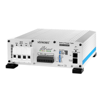
The main unit itself.

Mains Supply Cable with Shock-proof Plug

Includes the mains power supply cable.

Operating Manual

The manual itself.

Temperature Sensor 825

Includes the temperature sensor accessory.

Recommended Accessories

LCD Charge Control S, Remote Display and Control for all Operating Modes

Remote display and control unit for monitoring operations.

High-capacity Cutoff Relay 12 V; 200 A

High-capacity relay for specific bypass functions.

Switch Relay 12 V; 60 A

Standard switch relay for various control purposes.

Votronic VBCS 30/20/250 Triple Specifications

General IconGeneral
Input Voltage12V
Charging Current20A
Charging Voltage14.4 V (adjustable)
Solar Charge Controller Power250 W
Output Voltage12V
Max Output Current30A
Protection FeaturesOverload, Short Circuit, Reverse Polarity, Overheating

Related product manuals