ICON USER’S MANUAL: SECTION 6 VIRGINIA PANEL CORPORATION
6-1 For the most current information available, visit www.vpc.com.
6/7/18
ICON RECEIVER MODULE INSTALLATION AND REMOVAL
PART # 310 123 XXX
TOOLS REQUIRED
Phillips Head Screwdriver
NOTE: If the application requires, receiver modules can be
installed in the ITA and ITA modules in the receiver (must use
receiver Part # 310 123 103). If this is done, you must be sure
to switch the contacts as well (receiver contacts in a receiver
module and ITA contacts in an ITA module). You should also use
the keying kit to prevent attempted mating to a receiver or ITA
that has a standard module orientation.
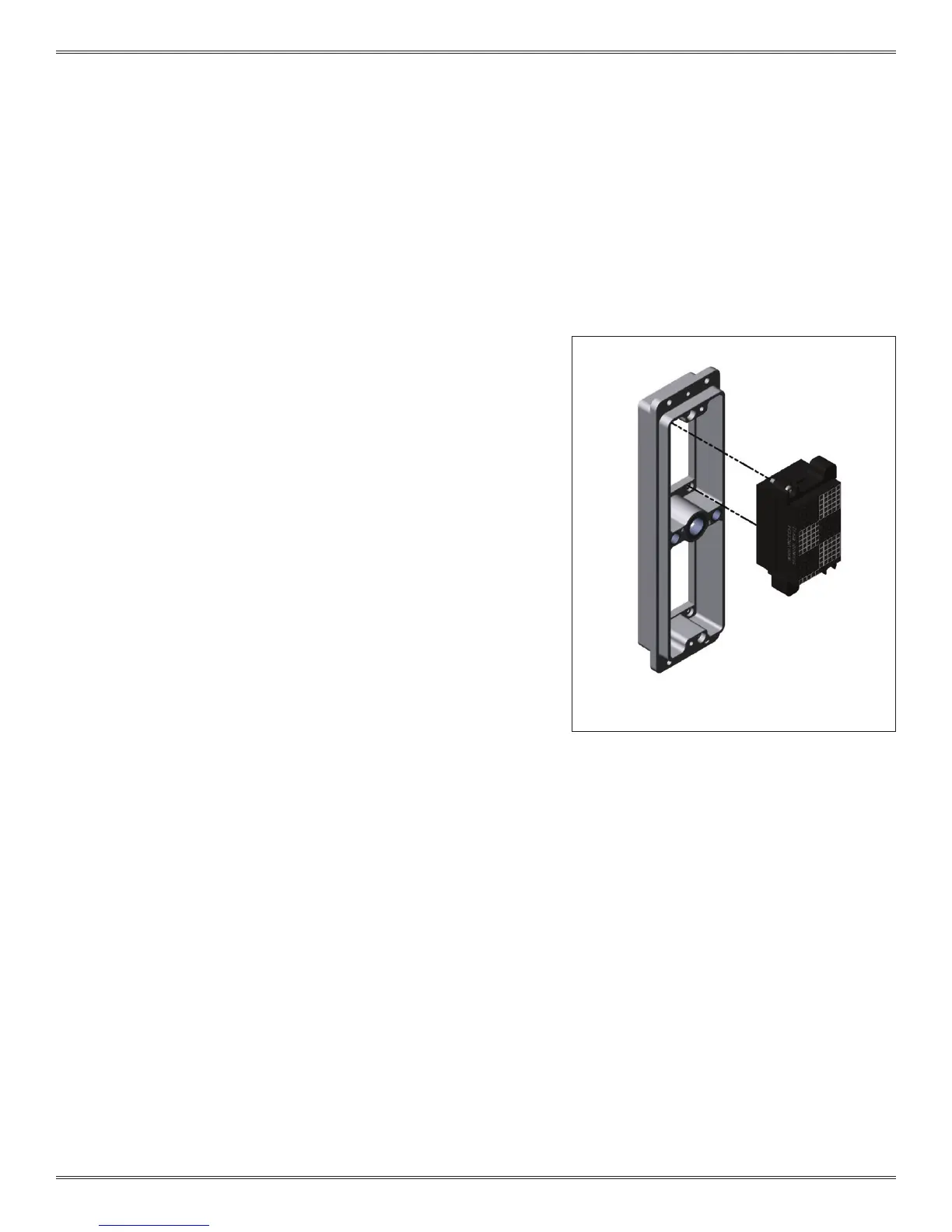
RECEIVER MODULE INSTALLATION INSTRUCTIONS
1. Place the module in the receiver until the upper and lower
module screws touch the mating holes in the frame. Install
modules such that Pin 1 is located at the top of the receiver
frame (Figure A).
2. Using a Phillips head screwdriver, tighten the top screw 1 to 2
full revolutions, while pushing lightly against the face of the
module.
3. Maintain this pressure while tightening the bottom screw 1 to
2 full revolutions.
4. Repeat this sequence until the module is seated. Torque the
screw to 1.5 in-lbs [0.16 Nm].
RECEIVER MODULE REMOVAL INSTRUCTIONS
1. To remove, loosen the top screw 1 to 2 full revolutions.
Loosen bottom screw 1 to 2 full revolutions.
2. Repeat this sequence until the module is separated from the
receiver.
NOTE: For optimum performance and system longevity,
distribute the contact load evenly throughout the module.
Figure A. The 2-56 module screws are designed with
a captive feature for loss prevention.
The iCon receiver is designed so the modules mount
from the rear. This allows the test technician to easily
mount wired cable assemblies without having to route
the connectors through the receiver frame.
 Loading...