ICON USER’S MANUAL: SECTION 5 VIRGINIA PANEL CORPORATION
6-2 For the most current information available, visit www.vpc.com.
6/7/18
ICON ITA MODULE INSTALLATION AND REMOVAL
PART # 410 123 XXX
TOOLS REQUIRED
Phillips Head Screwdriver
NOTE: If the application requires, receiver modules can be installed in
the ITA and ITA modules in the receiver (must use receiver Part #
310 123 103). If this is done, you must be sure to switch the contacts as
well (receiver contacts in a receiver module and ITA contacts in an ITA
module). You should also use the keying kit to prevent attempted mat-
ing to a receiver or ITA that has a standard module orientation.
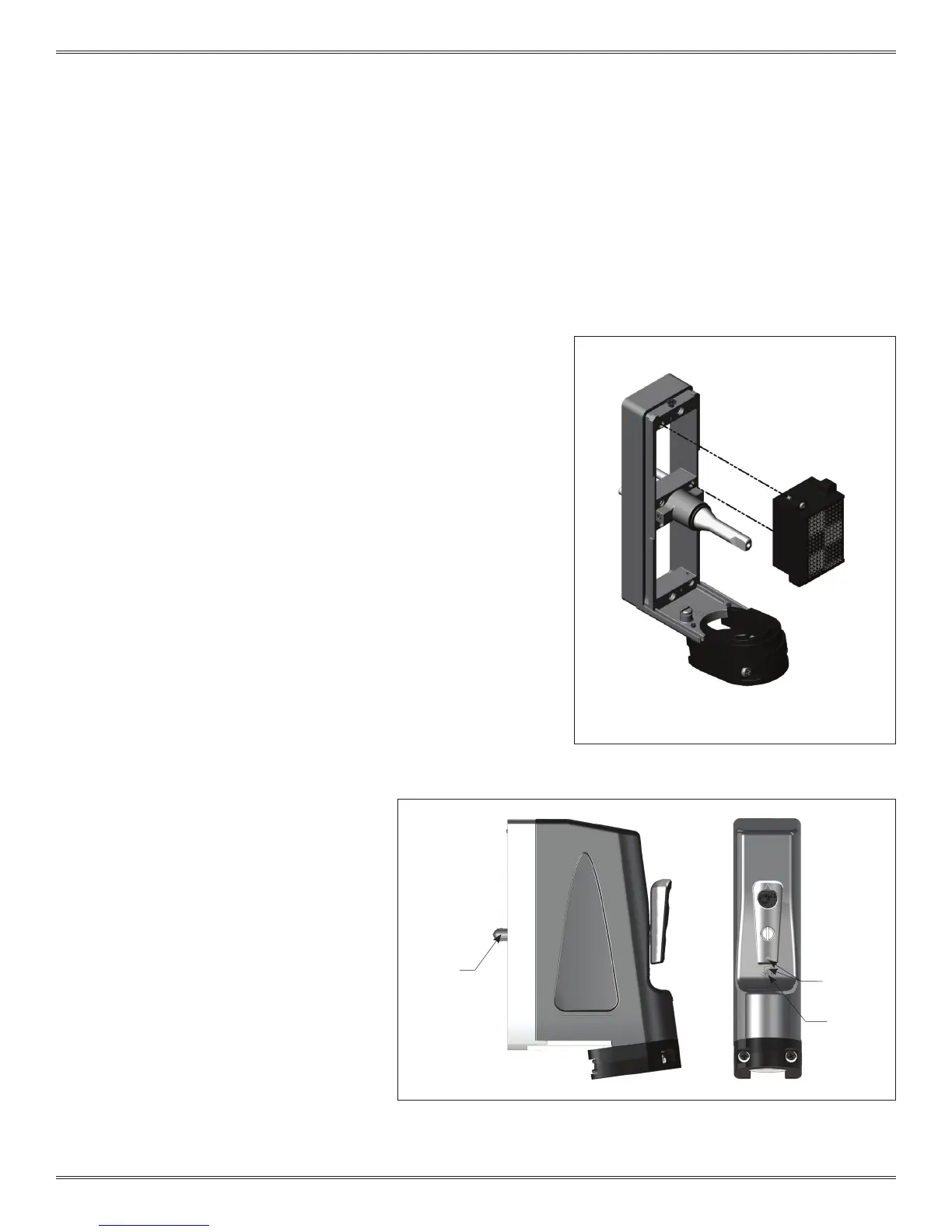
ITA MODULE INSTALLATION INSTRUCTIONS
1. Remove the cover. Refer to Section 4.
2. Place the module in the ITA until the upper and lower module
screws touch the mating holes in the frame. Install modules such
that Pin 1 is located at the top of the ITA frame (Figure A).
3. Using a Phillips head screwdriver, tighten the top screw 1 to 2 full
revolutions, while pushing lightly against the face of the module.
4. Maintain this pressure while tightening the bottom screw 1 to 2 full
revolutions.
5. Repeat this sequence until the module is seated. Torque the
screw to 1.5 in-lbs [0.16 Nm].
6. Reinstall the removable cover. It is important to
align the handle correctly (Figure B), or refer to
Section 4.
ITA MODULE REMOVAL INSTRUCTIONS
1. To remove, loosen the top screw 1 to 2 full
revolutions. Loosen bottom screw 1 to 2 full
revolutions.
2. Repeat this sequence until the module is
separated from the ITA.
NOTE: For optimum performance and system
longevity, distribute the contact load evenly
throughout the module.
Figure A. Make sure position 1 on the ITA module
aligns with position 1 on the receiver module.
Figure B. If the engagement mechanism is extended beyond the alignment pins
the handle should be attached in the “OPEN” position. Open is indicated by
aligning the raised circles on the handle and cover and revealing the “OPEN”
text.
ENGAGEMENT
MECHANISM
EXTENDED
RAISED
CIRCLE
OPEN
 Loading...