ICON USER’S MANUAL: SECTION 7 VIRGINIA PANEL CORPORATION
7-1 For the most current information available, visit www.vpc.com.
6/7/18
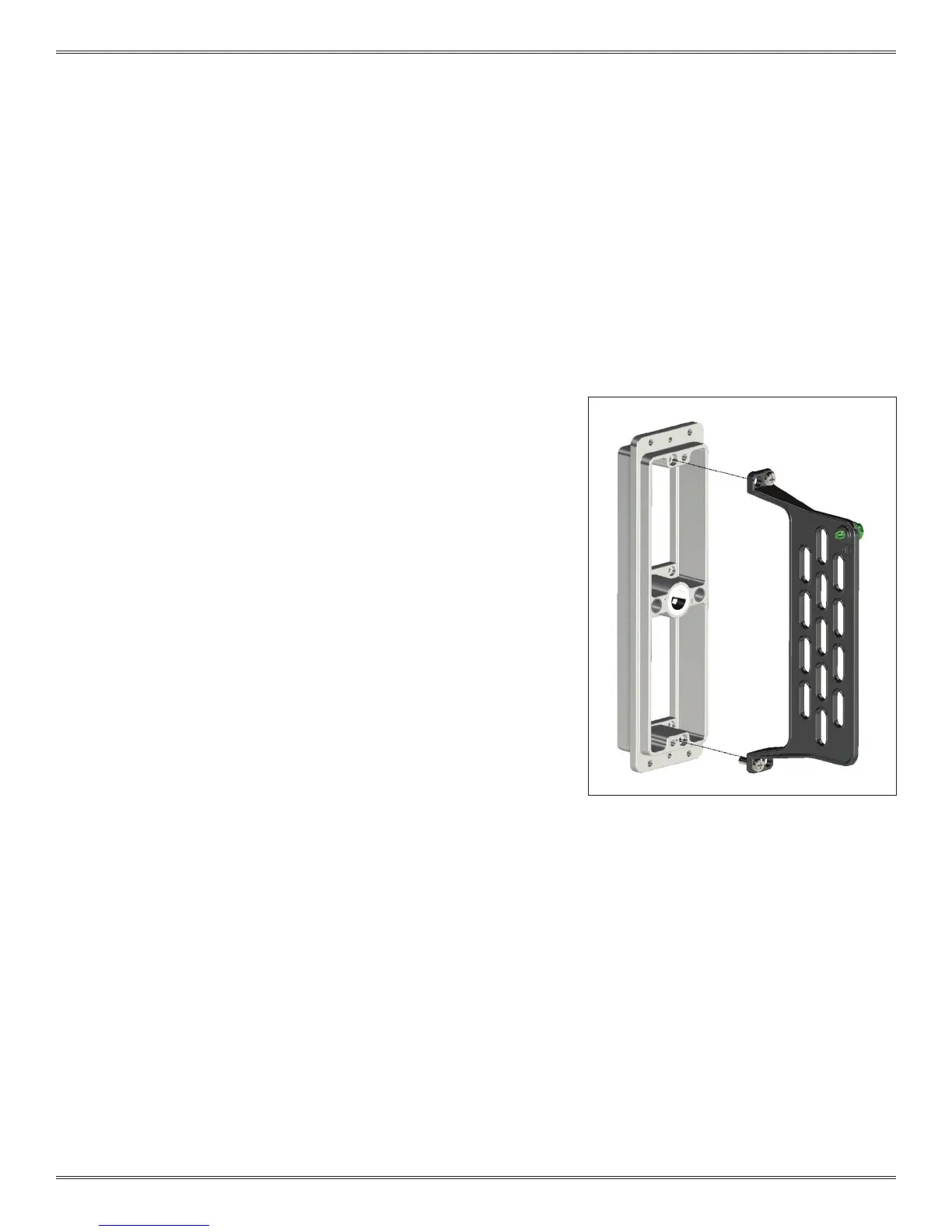
Figure A. Strain relief diagram showing proper
hole alignment.
TOOLS REQUIRED
Phillips Head Screwdriver
ASSEMBLY INSTRUCTIONS
1. Attach the strain relief to the iCon receiver on the wiring side
of the receiver frame (Figure A).
2. Fasten the strain relief to the iCon receiver frame with the
included screws and a Phillips head screwdriver.
3. Wires should be restrained a minimum of 2 inches from the
wiring face of the module. Six wire ties are included with the
strain relief.
NOTE: If using 8AWG, 10AWG or non-exible Coaxial wire in the
center module positions, the iCon Strain Relief stand-off Kit, Part # 310
113 582, will be required.
NOTE: When using the strain relief stand-off kit, install patchcords into
module before attaching strain relief.
ICON RECEIVER STRAIN RELIEF ASSEMBLY
PART # 310 113 456