ICON USER’S MANUAL: SECTION 4 VIRGINIA PANEL CORPORATION
4-3 For the most current information available, visit www.vpc.com.
6/7/18
ICON ITA COVER INSTALLATION
PART # 410 123 XXX
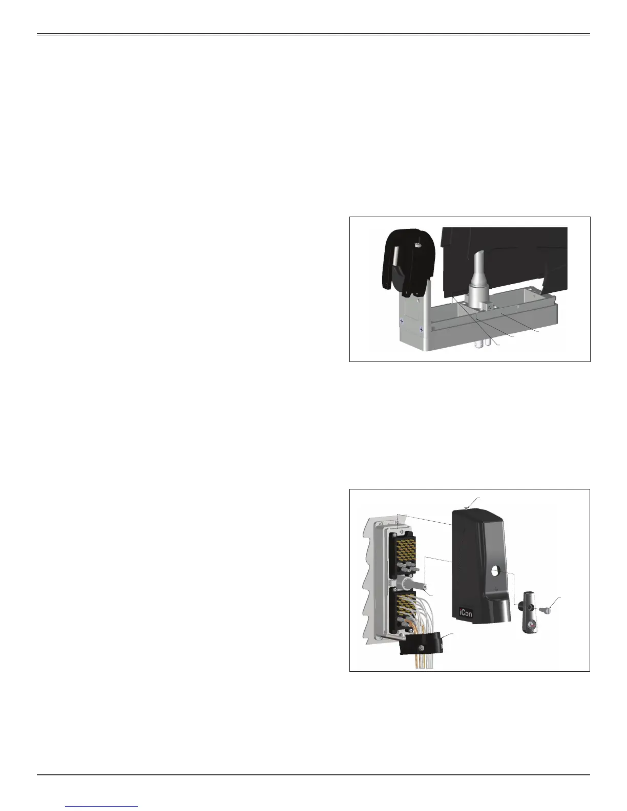
Figure B. Route the wires around the shaft to avoid
damage when the handle is attached.
SHAFT
SUPPLIED 6-32
FLATHEAD SCREW
CABLE CLAMP
ITA GROOVE
NOTCH AREA
COVER LIP EDGES
Figure A. The notch area provides an option of sliding
the cover half way as explained in the “ICON ITA COVER
REMOVAL” section.
COVER INSTALLATION INSTRUCTIONS CONTINUED
OPTION A: DISENGAGED POSITION
1. Place the cover onto the ITA as shown in Figure A. The lip will
align with the ITA groove.
2. Slide the cover onto the ITA frame until it is fully seated against
the cable clamp.
3. Place the handle (onto the shaft with the raised circles aligned.
Make sure wires are routed around the shaft and do not get
caught between the handle (Figure B) and shaft.
4. Position the supplied 6-32 shoulder screw into the handle and
tighten with a Flat Head screwdriver (Figure B).
5. Finally, tighten the captive screw at the top of the ITA securing
the cover to the ITA.
OPTION B: ENGAGED POSITION
1. Place the cover onto the ITA as shown in Figure A. The lip will
align with the ITA groove.
2. Slide the cover onto the ITA frame until it is fully seated against
the cable clamp.
3. Place the handle onto the shaft with the raised triangles lined up
as shown in Figure B.
4. Position the supplied 6-32 shoulder screw into the handle and
tighten with a Flat Head screwdriver (Figure B).
5. Finally, tighten the captive screw at the top of the ITA securing
the cover to the ITA.
 Loading...