EasyManua.ls Logo

VQ Models TIGER MOTH DH-82 User Manual

VQ Models TIGER MOTH DH-82
20 pages
To Next Page IconTo Next Page
Page #1 background imageLoading...
Page #1 background image
SPECIFICATIONS
Wingspan:......................................1400mm
Length:...........................................1180mm
Electric Motor:....................................750W
Glow Engine:.................... .46 2-T / .70 4-T
Radio:....................5 Channel / 4-5 Servos
Function: Ailerons-Elevator-Rudder-Throttle
WARNING! This radio controlled model is NOT a toy. If modified or flown carelessly it could go out of controll and
cause serious human injury or property damage. Before flying your airplane, ensure the air field is spacious enough.
Always fly it outdoors in safe areas and seek professional advice if you are unexperienced.
ACHTUNG! Dieses ferngesteuerte Modell ist KEIN Spielzeug! Es ist für fortgeschrittene Modellflugpiloten bestimmt,
die ausreichende Erfahrung im Umgang mit derartigen Modellen besitzen. Bei unsachgemässer Verwendung kann
hoher Personen- und/oder Sachschaden entstehen. Fragen Sie in einem Modellbauverein in Ihrer Nähe um
professionelle Unterstätzung, wenn Sie Hilfe im Bau und Betrieb benötigen. Der Zusammenbau dieses Modells ist
durch die vielen Abbildungen selbsterklärend und ist für fortgeschrittene, erfahrene Modellbauer bestimmt.
R/C Flugmodell R/C Airplane Model
ALL BALSA, PLYWOOD CONSTRUCTION AND ALMOST READY TO FLY
Anleitung / Instructions
TECHNISCHE DATEN
Spannweite ...................................1400mm
Lange ............................................1180mm
Elektroantrieb.................................... 750W
Verbrennerantrieb ...............7.45cc - 11.5cc
Fluggewicht .......................................3,5Kg
Fernsteuerung ........ 5 Kanal / 4 .. 5 Servos
RTF Weight: 3.Kg (will vary with equipment
use)
TIGER MOTH
DH-82
VQ No: VQA139R/Y/DK
Question and Answer IconNeed help?

Do you have a question about the VQ Models TIGER MOTH DH-82 and is the answer not in the manual?

VQ Models TIGER MOTH DH-82 Specifications

General IconGeneral
BrandVQ Models
ModelTIGER MOTH DH-82
CategoryToy
LanguageEnglish

Summary

Anleitung / Instructions

Technische Daten

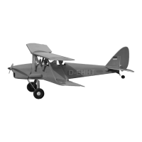
Key technical specifications of the model, including dimensions and weight.

Specifications

Lists technical details like wingspan, length, motor, engine, and radio specifications.

Safety Warning

Crucial safety information for operating the radio-controlled model responsibly.

Items Needed for Operation

Required Adhesives

Lists recommended adhesives like 5-minute epoxy and CA glue.

Required Tools

Outlines necessary tools not included, such as hobby knives and screwdrivers.

Engine Installation

Mounting and Alignment

Aligning engine mounts with fuselage marks and preparing for drilling.

Drilling and Blind Nut Attachment

Drilling the firewall and attaching blind nuts for engine mounting.

Engine Mounting and Securing

Attaching Engine Mounts

Securing engine mounts to the firewall using screws and washers.

Propeller Hub Distance

Positioning the engine to achieve the correct distance from the propeller hub to the firewall.

Engine Securing

Drilling the engine mounting plate and securing the engine to the mounts.

Electric Motor Installation

Mounting Plate Preparation

Marking and drilling the motor mounting plate for installation.

Firewall Drilling

Drilling holes in the firewall for the electric motor mount.

Motor Attachment

Securing the electric motor to the wooden motor mounting plate.

Horizontal Stabilizer Fitting

Pre-installation Preparation

Preparing the horizontal stabilizer, including elevator adjustment and fit testing.

Fuselage Marking

Tracing the stabilizer's outline onto the fuselage for precise alignment.

Covering Removal for Fit

Removing covering from the fuselage to ensure a snug fit for the stabilizer.

Horizontal Stabilizer Installation

Alignment and Gluing

Installing the stabilizer into the fuselage and securing it with CA glue.

Elevator Hinge Attachment

Attaching the elevator to its hinges within the horizontal stabilizer.

Vertical Stabilizer Installation

Rudder Separation

Detaching the rudder from the vertical fin.

Fuselage Slotting

Inserting the vertical fin into the designated slot on the fuselage.

Alignment and Cutting

Checking vertical alignment with a triangle and cutting covering.

Securing Vertical Stabilizer

Gluing the vertical stabilizer to the fuselage with CA glue.

Tail Wheel and Rudder Assembly

Rudder Drilling and Fitting

Drilling the rudder and fitting it into the vertical stabilizer hinge slots.

Torque Rod Marking

Marking the rudder for the tail gear torque rod mounting position.

Torque Rod Slot

Cutting a slot in the fuselage for the tail gear torque rod.

Rudder Securing

Gluing the rudder to the vertical stabilizer hinge with CA glue.

Control Horn Installation

Pre-cut Holes

Note that rectangular holes for control horn installation are pre-cut.

Horn Attachment

Attaching the plastic control horns to the aircraft surfaces.

Main Landing Gear Installation

Landing Gear Preparation

Preparing the main landing gear components, including drinking straws.

Gear Mounting

Attaching the main landing gear to the fuselage using screws.

Left/Right Assembly

Assembling the landing gear components, ensuring correct left/right fitting.

Main Landing Gear Wheel Attachment

Wheel Collars

Installing 2mm ID collars for securing the wheels.

Wheel Securing

Attaching the wheels to the landing gear using 1.5mm screw sets.

Servo and Linkage Setup

Glow Engine Configuration

Installing rudder, elevator, and throttle servos for glow engine setup.

Electric Motor Configuration

Installing rudder and elevator servos for electric motor setup.

Wing Strut Installation

Strut Attachment

Attaching the wing struts to the fuselage and wing structure.

Strut Connection

Connecting the wing struts using screws for rigidity.

Aileron Servo Installation

Aileron Hatch Removal

Removing the aileron access hatch to install the servo.

Servo Mounting

Installing the aileron servo into the wing structure.

Low Wing Control Linkages

Dowel Installation

Inserting wooden dowels into the low wing for linkage attachment.

Linkage Assembly

Connecting control cables and ensuring proper left/right (L/R) routing.

Cable Management

Securing control cables and managing excess length.

High Wing Control Linkages

Linkage Routing

Routing control cables for the high wing, noting pre-marked holes.

Cable Securing

Attaching and managing control cables for the high wing assembly.

Rod Exit Guide Installation

Guide Attachment

Installing the rod exit guide to facilitate control rod movement.

Wing Installation

Magnetic Hatch Removal

Removing the magnetic hatch to access the wing mounting area.

Wing Mounting

Securing the wings to the fuselage using nylon bolts and aluminum tubes.

Cable and Wing Brace

Wing Brace Attachment

Installing short and long braces for wing support.

Cable Connection

Connecting control cables to the wing brace system.

Fiberglass Cowl Installation

Cowl Attachment

Securing the fiberglass cowl to the front of the fuselage.

Center of Gravity (CG) and Balance

CG Location

Identifying the ideal center of gravity (CG) location for the aircraft.

Balancing Procedure

Steps to balance the airplane, including adjusting battery position for correct CG.

Lateral Balance

Achieving lateral balance by adding weight to the lighter wing half.

Control Surface Throws

Rudder Throw

Specifying the recommended throw amount for the rudder control surface.

Aileron Throw

Specifying the recommended throw amount for the aileron control surface.

Elevator Throw

Specifying the recommended throw amount for the elevator control surface.

Throw Adjustment Advice

Guidance on adjusting control throws for optimal flight performance.

Related product manuals