VRG CONTROLS LLC. 8 of 39 MAY 2021
RCVC 3000 - Red Circle Valve Controller
Installation, Operation, Maintenance Manual
#6 Edit Fail Modes
1. Apply 24 VDC Power Supply to RCVC
2. Apply Command Signal to RCVC
3. SHORT PUSH Navigation Wheel on RCVC Head
to enter MANUAL mode.
4. LONG PUSH Navigation Wheel on RCVC Head to
enter Menu mode.
5. Select “Application” and SHORT PUSH to enter.
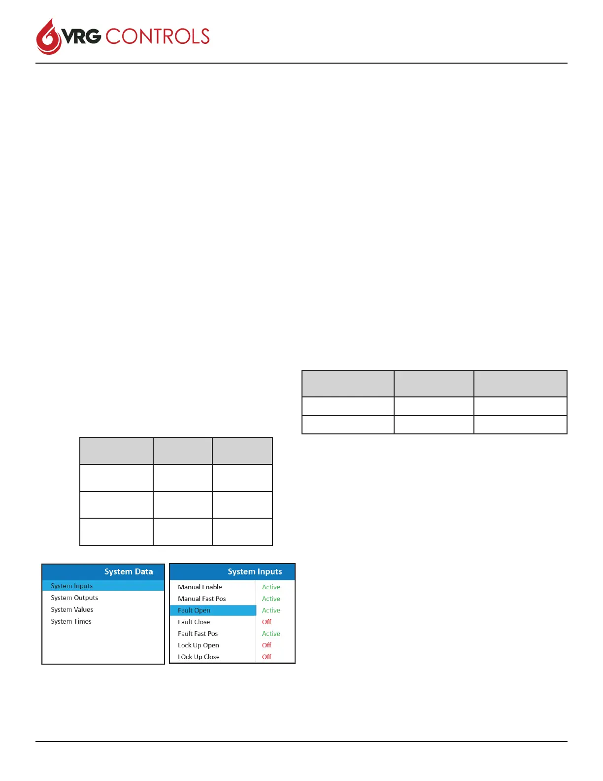
6. Select “System Data” and SHORT PUSH to enter.
7. Select “System Inputs” and SHORT PUSH to
enter.
8. For FAIL OPEN Mode:
A. Select Line 8 - “Fault Open” and Click
Radio Button Current Status = “ACTIVE”
B. Select Line 9 - “Fault Close” and Click
Radio Button Current Status = “OFF”
9. For FAIL CLOSED Mode:
A. Select Line 8 - “Fault Open” and Click
Radio Button Current Status = “OFF”
B. Select Line 9 - “Fault Close” and Click
Radio Button Current Status = “ACTIVE”
10. For FAIL LAST Mode:
A. Select Line 8 - “Fault Open” and Click
Radio Button Current Status = “OFF”
B. Select Line 9 - “Fault Close” and Click
Radio Button Current Status = “OFF”
#7 Edit Lockup Mode
1. Apply 24 VDC Power Supply to RCVC
2. Apply Command Signal to RCVC
3. SHORT PUSH Navigation Wheel on RCVC Head
to enter MANUAL mode.
4. LONG PUSH Navigation Wheel on RCVC Head to
enter Menu mode.
5. Select “Application” and SHORT PUSH to enter.
6. Select “System Data” and SHORT PUSH to enter.
7. Select “System Inputs” and SHORT PUSH to
enter.
8. For LOCKUP OPEN Mode:
A. Select Line 11 - “Lockup Open” and Click
Radio Button Current Status = “ACTIVE”
B. Select Line 12 - “Lockup Close” and Click
Radio Button Current Status = “OFF”
9. For LOCKUP CLOSED Mode:
A. Select Line 11 - “Lockup Open” and Click
Radio Button Current Status = “OFF”
B. Select Line 12 - “Lockup Close” and Click
Radio Button Current Status = “ACTIVE”
1. Apply 24 VDC Power Supply to RCVC
2. Apply Command Signal to RCVC
3. SHORT PUSH Navigation Wheel on RCVC Head
to enter MANUAL mode.
4. LONG PUSH Navigation Wheel on RCVC Head to
enter MENU mode.
5. Select “Application” and SHORT PUSH to enter.
6. Select “System Data” and SHORT PUSH to enter.
7. Select “System Values” and SHORT PUSH to
enter.
8. Select Value 4 Open Limit and SHORT PUSH to
enter.
A. Set Open Limit to desired value when
Lockup needs to engage.
9. Select Value 5 Close Limit and SHORT PUSH to
enter.
A. Set Close Limit to desired value when
Lockup needs to engage.
Mode Line 8 -
Fault Open
Line 9 -
Fault Close
Fail OPEN
Loss 4-20 mA
ACTIVE OFF
Fail CLOSED
Loss 4-20 mA
OFF ACTIVE
LOCK LAST
Loss 4-20 mA
OFF OFF
Mode Line 11 -
LOCKUP OPEN
Line 12 -
LOCKUP CLOSED
LOCKUP OPEN ACTIVE OFF
LOCKUP CLOSED OFF ACTIVE
 Loading...