EasyManua.ls Logo

VSI VSN-104Z - User Manual

VSI VSN-104Z
23 pages
Print Icon
To Next Page IconTo Next Page
Loading...
Page 1 / 23
VSN-104Z
INSTRUCTION MANUAL
Head : VSH-10Z
Controller : VSC-104Z
Copyright 2014 VSI Co., Ltd. All rights reserved
Contents of this publication may not be reproduced in any
form without the written permission of VSI Co., Ltd.
Question and Answer IconNeed help?

Do you have a question about the VSI VSN-104Z and is the answer not in the manual?

Summary

Product Markings and Indications

Domestic Version Product Markings

Details product markings for the domestic version, including safety symbols and warnings on the case.

International Version Product Markings

Details product markings for the international version, including safety symbols and warnings on the case.

Component Identification and Functions

VSH-10 Z Head Unit Components

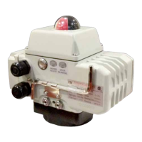
Identifies and describes the VSH-10Z head unit's parts, including the X-ray window, LCD, and indicators.

VSC-104 Z Controller Unit Components

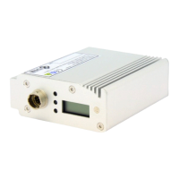
Identifies and describes the VSC-104Z controller's front and rear panel components, indicators, and connectors.

Installation and Operation Procedures

Head Unit Installation

Step-by-step guide for physically installing the head unit in a shielded location and connecting it.

Controller Power-On and Setup

Details the procedure for powering on the controller and initial connection setup.

Ionizer Irradiation On;Off Control

Explains how to activate and deactivate ionizer irradiation using the controller's Run/Stop button.

Controller Status Monitoring and Maintenance

Head Failure Status Indicators

Describes controller indicators and LCD messages displayed when the head unit experiences a failure.

Controller Cumulative Time Reset

Outlines the process for resetting the controller's cumulative operating time after 10,000 hours.

Signal Interface Connections

Controller Rear Panel Signal Ports

Details the pin assignments and functions for the DSUB 15-pin connector on the controller's rear panel.

Interlock Signal Setup and Safety

Explains how to set up the interlock signal for safe operation, covering both ON and OFF states and safety features.

Remote Control Functionality

Remote Control Mode 1 Signals

Details the remote control signal logic for Control Mode 1 (momentary operation) using specific pins.

Remote Control Mode 2 Signals

Details the remote control signal logic for Control Mode 2 (alternate operation) using specific pins.

Remote Operation Workflow

Outlines the sequential steps required to perform remote operation of the ionizer, including interlock checks.

Signal Input;Output Circuitry

Internal I;O Circuit Schematic

Provides a schematic diagram of the internal circuitry for signal input and output ports.

LED Output & Relay Input Example

Illustrates an example of using LED output drive and relay input for signal connections to the controller.

TTL Output & Semiconductor Input Example

Shows an example of using TTL output drive and semiconductor contact input for signal interfaces.

Photocoupler Input;Output Example

Demonstrates an example of using photocoupler input and output for signal connections to the controller.

General Safety Instructions

X-ray Shielding Guidelines

Provides guidance on shielding materials and thicknesses for user safety from X-ray radiation emissions.

Static Decay Time Performance

Decay Time Measurement Graph

Illustrates decay time for static removal using a graph and explains the measurement method.

Product Technical Specifications

Head Unit Specs

Lists dimensions, X-ray tube, emission, weight, and LED indicators for the head unit.

Controller Unit Specs

Lists dimensions, fuse, weight, power, temp, indicators, and functions for the controller.

Included Product Components

Package Contents List

Details the quantities and types of head units, controller, cables, and mounting hardware included in the package.

Physical Dimensions

Head Unit Physical Dimensions

Provides detailed dimensional drawings and measurements for the VSH-10Z head unit.

Controller Unit Physical Dimensions

Presents detailed dimensional drawings and measurements for the VSC-104Z controller unit.

Overview

The VSN-104Z is an instruction manual for a static elimination device, consisting of a Head (VSH-10Z) and a Controller (VSC-104Z). This device utilizes soft X-rays to ionize the air, thereby eliminating static electricity.

Function Description

The core function of the VSN-104Z is static electricity removal through soft X-ray irradiation. The Head (VSH-10Z) is the component responsible for emitting these soft X-rays. It features a "Soft X-ray window" through which the X-rays are irradiated to ionize the air, neutralizing static charges.

The Controller (VSC-104Z) manages the operation of up to four heads. It provides power to the heads and allows for control over the X-ray irradiation process. The controller includes various indicators and switches for monitoring and operating the system.

Key functional components on the Head include:

  • Soft X-ray window: The output point for the soft X-rays.
  • Timer LCD: Displays the cumulative usage time of the head in hours.
  • Run Indicator (Green Light): Illuminates when soft X-ray irradiation is active and static elimination is in progress.
  • Timer Indicator (Yellow Light): Lights up when the head has operated beyond its guaranteed operation time (10,000 hours), signaling a potential need for replacement.
  • Alarm Indicator (Red Light): Activates in case of abnormal head operation, indicating a fault.
  • Controller Connector: A 12-pin connector for linking the head to the controller.

The Controller (VSC-104Z) offers comprehensive control and monitoring capabilities:

  • Power (Green Light): Indicates that the controller is powered on.
  • Interlock (Yellow Light): A safety indicator that lights up when the interlock system is connected, making the ionizer ready for irradiation.
  • Head Fail (Red Light): Illuminates when an abnormal operation occurs in any connected head.
  • Remote mode (Green Light): Indicates that the controller is operating under remote control (mode1 or mode2).
  • Head Indicator (Blue Light): Shows the status of each connected head channel. It flashes if a head has exceeded its operating time and lights up if a head fails.
  • Timer LCD: Displays the cumulative operation time of the controller in hours.
  • Time Reset Switch: Allows resetting the controller's operation time, specifically for accumulated times over 10,000 hours, typically after replacing a head.
  • Run/Stop Switch: A manual switch to initiate or cease soft X-ray irradiation.
  • Head Connector: Connectors for attaching up to four heads via 12-pin cables.
  • Signal Output Connector: A D-SUB 15-pin connector for interfacing with external devices, providing various output signals (Power, Interlock ON, Normal operation, Abnormal operation) and accepting input signals for remote control (Remote SEL, Remote ON, Remote OFF, Interlock).
  • Ground Terminal: For grounding the controller.
  • AC Inlet: For connecting the AC power cable.

Usage Features

The VSN-104Z is designed for straightforward installation and operation, with a strong emphasis on safety and remote control capabilities.

Installation: The head unit should be fixed using its fixture bracket and supplied screws in a desired location, specifically within a shielded environment. The controller should be placed in an easily accessible location. The head and controller are then connected using the provided connection cable.

Operation Sequence:

  1. Connection: Ensure the head and controller are connected via the connection cable before powering on the controller.
  2. Power On: Turn on the power switch located on the rear panel of the controller. The power lamp on the front panel will illuminate.
  3. Interlock Input: The device requires an interlock signal to be ready for irradiation. This is achieved by closing pins 14 and 15 of the DSUB I/O Connector on the rear panel. Once the interlock is closed, the "Interlock" lamp on the front panel lights up, indicating readiness.
  4. Ionizer Irradiation ON: Pressing the "Run/Stop" button on the front panel once initiates soft X-ray irradiation. During irradiation, the area around the "Run/Stop" button glows white, and an hourglass symbol appears on the LCD.
  5. Ionizer Irradiation OFF: Pressing the "Run/Stop" button again stops the irradiation. The white light and hourglass symbol will disappear.

Remote Control: The VSN-104Z supports remote control through the D-Sub 15-pin connector, offering two modes:

  • Control Mode 1 (Momentary):
    • Remote On: Closing D-Sub 15-pin terminals 11 and 13 initiates soft X-ray irradiation. The irradiation continues as long as these terminals remain closed.
    • Remote Off: Opening D-Sub 15-pin terminals 11 and 13 stops irradiation.
  • Control Mode 2 (Alternate):
    • Remote On: Closing D-Sub 15-pin terminals 11 and 13 for more than 50ms initiates soft X-ray irradiation.
    • Remote Off: Closing D-Sub 15-pin terminals 12 and 13 for more than 50ms stops irradiation.

Safety Features: The device incorporates critical safety features to protect users from X-ray exposure:

  • Shielding Requirement: The head must be installed in a shielded facility. The manual provides guidance on appropriate shielding materials and thicknesses based on distance from the X-ray source.
  • Interlock System: The interlock mechanism is crucial. If an enclosure door (connected to the interlock) is opened during X-ray irradiation, the interlock terminal opens, and irradiation automatically stops. The "Interlock" lamp and "Run/Stop" switch on the controller turn off. When the interlock is closed again, the device returns to a safe, ready status.
  • Warning: Direct exposure to soft X-rays can cause damage, emphasizing the necessity of the interlock connection and proper shielding.

Maintenance Features

The VSN-104Z includes features to monitor device health and facilitate maintenance.

Head Operation Monitoring:

  • Timer LCD (Head): Each head has its own LCD displaying its individual usage time. This helps track the operational lifespan of each head.
  • Timer Indicator (Yellow Light): When a head exceeds its guaranteed operation time of 10,000 hours, its yellow timer indicator lights up. While the head may continue to operate normally, this serves as a warning that replacement may be due soon.
  • Alarm Indicator (Red Light): This indicator on the head signals abnormal operation, prompting investigation or replacement.
  • Head Fail (Red Light on Controller): If any connected head experiences abnormal operation, the "Head Fail" red light on the controller illuminates, and the corresponding "Head Indicator" (blue light) for that channel also lights up. The controller's LCD will additionally display "Err" to indicate a fault.

Controller Operation Monitoring:

  • Timer LCD (Controller): The controller's LCD displays the cumulative irradiation time of the controller itself, not linked to individual heads. This time is in hours and is used to gauge the overall system's operational duration.
  • Time Reset Switch: This switch allows resetting the controller's cumulative operation time to 0 hours. This is particularly useful after replacing a head, ensuring that the new head's operational cycle can be accurately tracked from the start. The reset function is only available when the accumulated time exceeds 10,000 hours.
  • Head Indicator (Blue Light on Controller): This indicator not only shows the status of each channel but also flashes if a head has exceeded its operational time, providing a centralized view of head maintenance needs.

These features collectively enable users to monitor the operational status of both individual heads and the overall system, identify potential issues, and perform timely maintenance, such as head replacement, to ensure continuous and safe operation.

VSI VSN-104Z Specifications

General IconGeneral
CategoryController
Input Voltage24VDC
Output Voltage24VDC
Output Current4A
Storage Temperature-20°C to +70°C
Dimensions120mm x 80mm x 40mm
Weight300g
Protection ClassIP20

Related product manuals