Installation guide
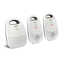
DM271
DM271-102
DM271-110
Wireless Monitoring System
with Safe & Sound
®
Digital Audio Monitor
Go to
www.vtechphones.com
to register your product
for enhanced warranty
support and the latest
VTech product news.
Specific ations are subject to c hange without notice.
© 2015 for VTech Communi cations, Inc.
All rights r eserved. 12/15. DM271_IG_V2.0
Document o rder number: 96-0108 88-020-100
4
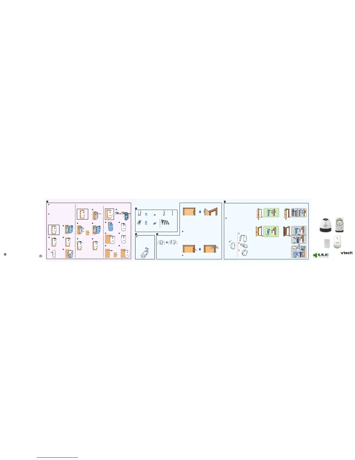
Mount
5
Mount
This sensor m ust be mounted vertic ally on wall.
Do not mount th e Motion Sensor in a horizo ntal
orientati on, or flat on the ceiling.
If you drill th e holes into an object oth er than a
stud, inser t the screw anchors in to the holes and
tap gently o n the ends with a hammer unt il the
screw anch ors are flush wit h the wall or ceiling.
You can choose to mou nt the sensor with the
mounting ta pe first. Remove the mount ing tape
and use screw s later if you deci de to mount it at
that locat ion for long term.
•
•
•
Mount with screws
(Optional)
Insert screw
anchors if
necessary.
Mount on the wall - with fixed angle Mount on the wall - with rotate detection angle
Mount with screws
Mount on the wall - with fixed angle
This screw should only
be fully secured after
you adjusted the angle.
Unscrew
first.
(Optional)
Insert screw
anchors if
necessary.
Tighten the screws
after you slided the
sensor over them.
Tighten
the screw.
Tighten
the screw.
Tighten
the screw.
> 1 cm
(0.4 inch)
> 1 cm
(0.4 inch)
> 1 cm
(0.4 inch)
1 cm
(0.4 inch)
Without spacer With spacer (optional)
Mount the sensor unit
We recommend you mo unt the magnet uni t on a
door, window, or medic ine cabinet, an d mount the
sensor unit on i ts respecti ve frame.
You can use the spacers pr ovided if there i s a
differenc e in level between th e door and the
frame. The space r will help to align yo ur sensor
to the correc t height. You can also use a s pacer
if the frame is too n arrow or has some de corative
molding.
You can mount the sen sor unit with mounting t ape first,
and then use s crews later if you decide to mo unt it at
that locat ion for long term.
Make sure the mo unting surface is cle an. A textured
surface or any imp erfections to a smooth sur face can
keep the mountin g tape from maki ng a strong bond.
Align the mag net unit with sensor uni t when mounting.
The distan ce between the sensor un it and magnet unit
must be less t han 1 cm (0.4 inch).
•
•
•
•
With spacer (optional)
Without spacer
* The door fram e is thicker than
the door.
* The door is
thicker tha n
the door fra me.
3
Check and locate
Check your Open/Closed
sensor before use
Test the sensor signal strength
After testing t he sensor sign al strength, mar k the mounting lo cation
on the door, window, or med icine cabin et and its respec tive frame.
Then, remove the ad hesive tape and pro ceed to the moun ting
process.
Use your parent unit t o enter the Senso r settings me nu, and then
select the Ch eck signal me nu. Follow the steps to te st the sensor ’s
signal stren gth, and then exit t he sensor setup mo de. Make sure
there is a good s ignal received w hen you open the d oor as usual.
Make sure both baby u nit and parent unit
are on. Then, separ ate the sensor uni t
from the magnet u nit.
The parent unit wi ll emit an aler t tone,
and announce “O pen/Closed X* is open ”.
The screen wil l display Open /Closed X
is open.
If your package includes an Open/Closed sensor,
please read the following section.
Open/Closed sensor installation
1
Parts checklist
2
Power on
The batteries are pre-installed in
your Open/ Closed sensor.
The Open/ Closed sensor is
already
pre-registered to the baby monitor.
The batteries operate properly
under the temperature between
0°F (-18°C) and 130°F (55°C).
•
•
•
Use adhesive tape to hold the sensor temporarily in place.
Mount the sensor to a higher position to avoid obstacles or blockages.
Depending on surroundings and obstructing factors, like walls or
cabinets, the sensor may not transmit to the baby unit properly.
•
•
If No signal o r Weak signal message is di splayed in sensor setup mo de,
or if you do not rec eive an alert when you ope n the door, move the baby unit
closer to the m ounting location or m ove the sensor cl oser to the baby unit.
•
Sensor unit Magnet unit
Spacer for
sensor unit
(optiona l)
Double- sided
mounting ta pe C
Spacers for
magnet unit
(optiona l)
Large screw x 2
(for spacer o f
sensor unit )
Small screw x 2
(for fixing se nsor
unit’s back c over
on spacer)
Double- sided
mounting
tape A
1 set for DM251-102
Double- sided
mounting
tape B
The door imag es in this installati on guide are for concept ual reference only.
•
*
X refers to the sys tem-assigned numb er
of the s ensor.

 Loading...