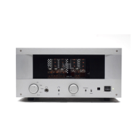
IT-85 Integrated amplifier
Owner’s Manual
VTL
22
the VTL IT-85 Integrated amplifier.
For checking the bias you should take the unit and this procedure to your authorized
VTL dealer and ask them to check the bias for you.
Notes for the service/installing technician:
Bias measurements are preferably taken with a digital multimeter equipped with the
auto-ranging feature. If you don’t have such a meter you can purchase one at a local
electronics supply store such as Radio Shack. The Radio Shack catalog numbers for
usable multimeters are 22-166, 22-167, 22-163, 22-174 or even 22-179.
Use the following procedures to measure and adjust the bias setting:
1. Make sure that the IT-85 is powered off. Remove the protective metal
cage of the IT-85, and make sure that there is sufficient room around the
unit for you to access the bias measurement points at the back edge of the
IT-85. Set the multimeter for resistance measurement (ohms). (Consult
the owner’s manual of the multimeter to make sure that you have used the
correct settings.)
2. Connect the negative (black, “-“) probe from the multimeter to the ground
point on the IT-85or the negative (“-“) speaker binding post of the
amplifier.
3. Consult the following figure for the locations of the bias measurement
points on the IT-85’s top deck. Insert the positive (red, “+”) probe of the
multimeter into each bias measurement point. The resistance reading on
each point should be 10 ohms, within a 10% range. If the resistance
reading is outside the acceptable range, please consult the VTL factory
customer service department immediately. Repeat the measurement
procedure for all 4 bias measurement points.
4. Remove the multimeter probes from the IT-85. Check to make sure that
the IT-85 is connected to a loudspeaker or a load resistor. Power on the
IT-85 and let it warm up for about 10-15 minutes so that the tubes
become stabilized. Either short the input or put the IT-85 in the mute
state (or turn the volume down) to make sure that no signal is coming
from the preIT-85 section.
5. Change the meter setting to measure DC voltage. Insert the negative
probe (black) from the multimeter into the ground point on the IT-85 or
the negative speaker binding post of the IT-85 fitting it into the post
where the speaker cable is connected. Insert the positive probe into the
bias measurement point of each tube going from the #1 point to #4. The