P.O. Box 696
■
Louisville, KY 40201
■
Toll-free: 1-800-814-2028
■
Local: 502-778-2791
■
Quote & Order Fax: 1-800-444-0602
a division of ITW Food Equipment Group LLC
STEAM
F-35471 (04/10)
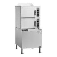
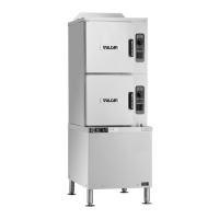
C24EA FLOOR SERIES
ELECTRIC CONVECTION STEAMER
ON CABINET BASE
NOTE: In line with its policy to continually improve its products, Vulcan reserves the right to change materials and specications without notice.
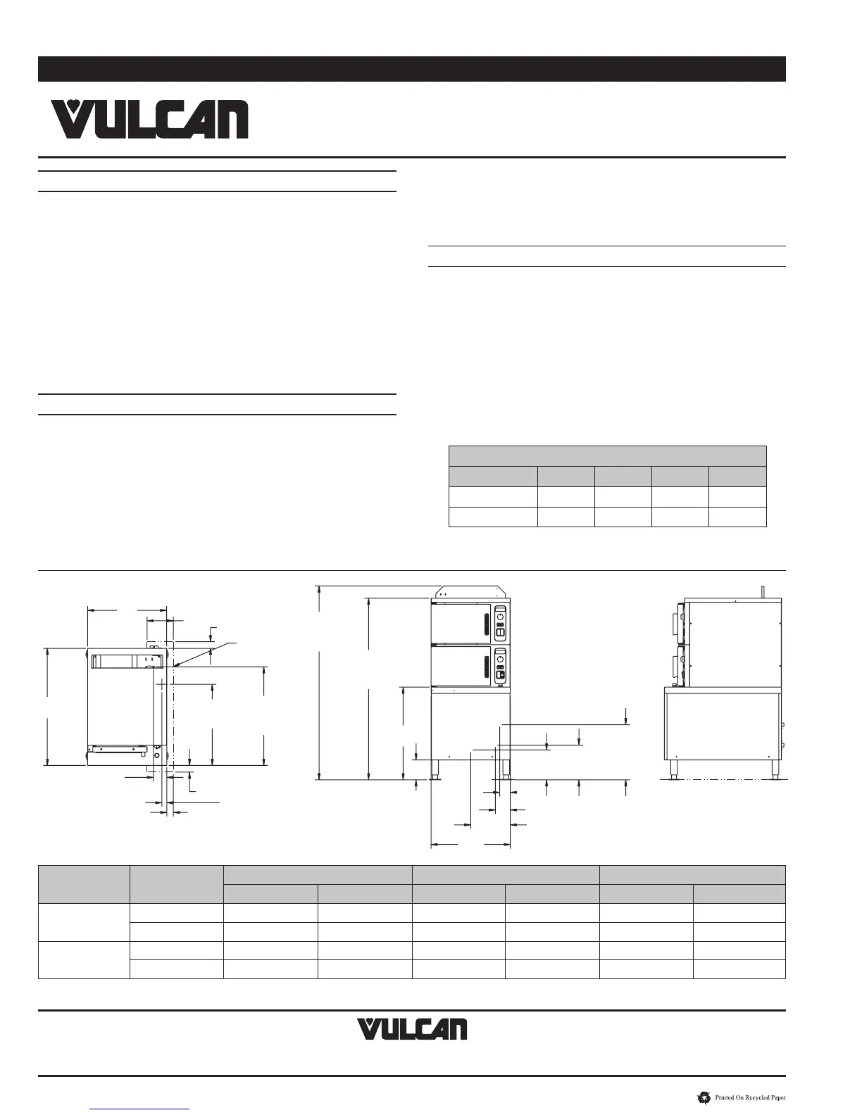
SERVICE CONNECTIONS:
ELECTRICAL CONNECTION: Single point supply 1
1
⁄
8
" (29 mm) dia.
(
3
/
4
" conduit).
DRAIN: Condenser box, compartment and generator, 1
1
⁄
2
" NPT.
(Provide an open air gap type drain within 12" of condenser box
and for best results at a distance so steam vapors will not enter the
steamer from underneath the control area. Do not connect solidly to
any drain connection.)
GENERATOR WATER SUPPLY:
3
⁄
4
" (19 mm) male hose thread to
generator, cold water ow rate .5 gpm @ minimum 20 to maximum
60 psi. (138-414 kPa).
CONDENSING WATER SUPPLY:
3
⁄
4
" (19 mm) male hose thread to
condenser, cold water ow rate .5 gpm @ minimum 20 to maximum
60 psi. (138-414 kPa).
WATER QUALITY STATEMENT:
The fact that a water supply is potable is no guarantee that it is
suitable for steam generation. Your water supply must be within these
general guidelines:
SUPPLY PRESSURE 20 - 60 psig
HARDNESS* less than 3 grains
SILICA less than 13 ppm
TOTAL CHLORIDE less than 4.0 ppm
pH RANGE 7-8
UN-DISSOLVED SOLIDS less than 5 microns
* 17.1 ppm = 1 grain of hardness
Other factors affecting steam generation are iron content, amount
of chloridation and dissolved gases. Water supplies vary from state
to state and from locations within a state. Therefore it is necessary
that the local water treatment specialist be consulted before the
installation of any steam generating equipment.
NOTE:
• Dimensionswhichlocatetheaboveconnectionshaveatolerance
of + or -3" (+ or -75 mm). Normal dimensions are in inches.
Dimensions in ( ) are in millimeters.
• Installationofbackowpreventers,vacuumbreakersandother
specic code requirements is the responsibility of the owner and
installer. It is the responsibility of the owner and installer to comply
with local codes.
• Donotuseplasticdrains.
• Thisapplianceismanufacturedforcommercialinstallationonly
and is not intended for home use.
MODEL Phase
208 V 240 V 480 V
kW Amps kW Amps kW Amps
C24EA6
1ø 17.2 81.25 17.2 79.1 17.2 N/A
3ø 17.2 48.2 17.2 51.3 17.2 21.4
C24EA10
1ø 25.6 121.2 25.6 110.4 25.6 N/A
3ø 25.6 71.2 25.6 67 25.6 31.8
NOTE: 3ø is an unbalanced load, and amps listed is the max on any leg. Refer to the Installation and Operation Manual for further details.
10.5
(267)
TREATED
WATER
9.0
(230)
ELECTRICAL
16.7
(424)
UNTREATED
WATER
6.0
(152)
24.0
(610)
12.0
(305)
3.2
(82)
4.5
(115)
28.0
(712)
6 PAN 58.7
(1490)
10 PAN 71.5
(1823)
6 PAN 55.0
(1397)
10 PAN 67.9
(1730)
35.5
(901)
24.0
(609)
8.0
(203)
2.0
(51)
NO OPEN
DRAIN
23.9
(607)
DRAIN
29.8
(758)
CONDENSATE
BOX VENT
2.0
(51)
2.0
(51)
2.1
(53)
DRAIN
4.0
(102)
CONDENSATE
BOX VENT
COMPARTMENT PAN CAPACITY
MODEL 1" 2
1
⁄
2
" 4" 6"
C24EA6 6 3 2 1
C24EA10 10 5 3 2
 Loading...