A product of VULCAN-HART LOUISVILLE, KY 40201-0696
F25105 (Rev. A, October 2007)
- NOTICE -
This Manual is prepared for the use of trained Vulcan Service
Technicians and should not be used by those not properly qualified.
If you have attended a Vulcan Service School for this product, you
may be qualified to perform all the procedures described in this
manual.
This manual is not intended to be all encompassing. If you have not
attended a Vulcan Service School for this product, you should read,
in its entirety, the repair procedure you wish to perform to
determine if you have the necessary tools, instruments and skills
required to perform the procedure. Procedures for which you do not
have the necessary tools, instruments and skills should be
performed by a trained Vulcan Service Technician.
Reproduction or other use of this Manual, without the express
written consent of Vulcan, is prohibited.
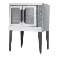
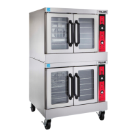
VC4ED SHOWN
SERVICE MANUAL
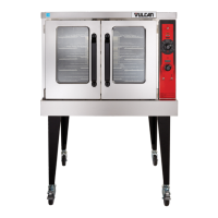
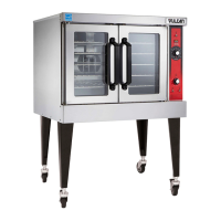
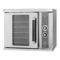
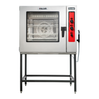
VC4E & VC6E
SERIES
FULL SIZE
ELECTRIC CONVECTION
OVENS
MODEL ML
VC4ES 126743
VC4ED 126744
VC4EC 126745
VC6ES 126746
VC6ED 126747
VC6EC 126748