EasyManua.ls Logo

W.E.S.T. Elektronik PAM-199-P User Manual

W.E.S.T. Elektronik PAM-199-P
48 pages
To Next Page IconTo Next Page
Page #1 background imageLoading...
Page #1 background image
Technical Documentation
PAM-199-P
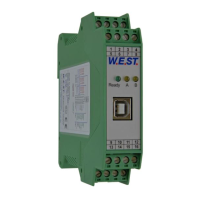
Power amplifier for all typical proportional valves

Table of Contents

Questions and Answers:

W.E.S.T. Elektronik PAM-199-P Specifications

General IconGeneral
BrandW.E.S.T. Elektronik
ModelPAM-199-P
CategoryAmplifier
LanguageEnglish

Summary

General Information

Order Number

Product identification and ordering codes for the PAM-199-P series.

Scope of supply

Details the included components and items that must be ordered separately.

Accessories

Lists optional accessories such as the Start-Up-Tool and programming cables.

Symbols used

Explanation of symbols for general information and safety warnings.

Legal notice

Company contact information, website, and disclaimer of liability.

Safety instructions

Critical safety precautions for installation, operation, and maintenance.

Characteristics

Device description

Physical overview, dimensions, and terminal pin assignments.

Use and application

Installation instruction

Guidelines for EMC-compliant installation and cable screening.

Commissioning

Step-by-step procedure for setting up and starting the device.

Function modes and technical description

General Information

Overview of module functionality selection and parameter saving.

LED Indications

Interpreting the status of the device via LED indicators.

Control of directional valves (195)

System structure and operation for controlling directional valves.

Control of two throttle and / or pressure valves (196)

System structure and operation for controlling dual pressure/throttle valves.

Control of proportional valves by preprogrammed values and ramp times (197)

System structure and operation for control via preprogrammed values.

Input connection (examples)

Illustrative examples of connecting various input devices.

Technical data

Detailed specifications and electrical characteristics of the module.

Parameter description

FUNCTION (Function mode)

Defines the operational mode (195, 196, or 197) of the module.

LG (Changing the language for the help texts)

Selects the language for user interface and help texts.

MODE (Switching between parameter groups)

Switches between standard and expert parameter modes.

SENS (Failure monitoring)

Activates/deactivates module monitoring functions.

CCMODE (Activation of the characteristic linearization)

Enables or disables characteristic linearization for valve control.

SOLENOIDS (One or two solenoids)

Adapts the amplifier for single or dual solenoid valves.

PIN:5 (Choice of the additional function of PIN 5)

Assigns additional functions to digital input PIN 5.

PIN:6 (Choice of the additional function of S1/PIN 6)

Defines the functionality of digital input PIN 6 (USCALE/RAMP).

USCALE (Output current scaling depending on PIN:6)

Scales output current based on PIN:6 setting.

ENABLE_B (Switching of the ENABLE Function)

Manages independent ENABLE signals for channels A and B.

LIM (Signal monitoring)

Monitors input signal range to detect faults like cable breaks.

POL (Output polarity)

Switches the output signal direction for valves.

AINA (Current- / Voltage input)

Selects input signal type for channel A (current or voltage).

AINB (Current- / Voltage input)

Selects input signal type for channel B (current or voltage).

AIN (Analogue input scaling)

Configures scaling for analogue input signals using linear equation.

AA (Ramp function/Acceleration time)

Sets ramp up/down times for two quadrant ramp function.

AB (Ramp function/Acceleration time)

Sets ramp up/down times for two quadrant ramp function.

AA (Ramp function)

Configures four quadrants ramp function for solenoid A and B.

RMODE (Choosing ramp function)

Switches between set point related and four quadrant ramp functions.

S (Presetting command values)

Sets eight possible command values determined by digital inputs.

RA (Ramp function / Acceleration time)

Sets ramp times based on RMODE and set points.

CCA (Characteristics linearization channel A)

Defines signal characteristic for channel A using a table/graph.

CCB (Characteristics linearization channel B)

Defines signal characteristic for channel B using a table/graph.

CC (Characteristics linearization)

Sets signal characteristic, positive for A, negative for B.

MIN (Overlap compensation)

Compensates for valve dead band (overlap).

MAX (output scaling)

Defines the maximum output signal (valve current).

TRIGGER (threshold value of MIN function)

Sets activation point for the MIN function's non-sensitive range.

CURRENT (Nominal output current)

Sets the nominal solenoid current for range reference.

DFREQ (Dither frequency)

Sets the frequency for the dither signal.

DAMPL (Ditheramplitude)

Sets the amplitude for the dither signal.

PWM (PWM frequency)

Sets the PWM frequency for valve control.

ACC (Auto adaptation of the closed loop current controller)

Sets automatic or manual adjustment for current controller parameters.

PPWM (Solenoid current controller P gain)

Parameterizes the proportional gain for the solenoid current controller.

IPWM (Solenoid current controller I gain)

Parameterizes the integral gain for the solenoid current controller.

PROCESS DATA (Monitoring)

Displays variable process data for monitoring and analysis.

Appendix

Failure monitoring

Lists possible error sources and their characteristics.

Troubleshooting

Provides causes and solutions for common faults and errors.

Notes

Related product manuals