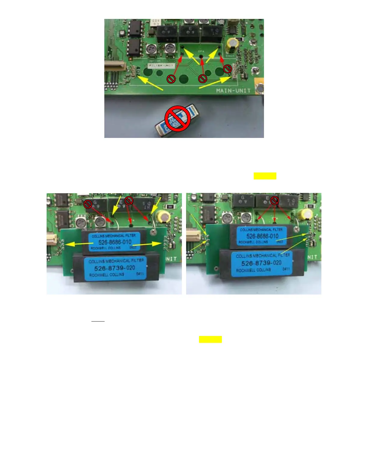
Figure 4
10. Locate the OBF-817 to be installed and notice the two (2) wires coming off on the OBF-817. Now examine
Fig. 4 and observe the two holes denoted by yellow arrows in the CF4 area (where the MuRata filter was
mounted) and the two (2) connectors (J20 and J21) also shown by yellow arrows. DO NOT insert anything into
the holes in CF4 denoted by the red arrows.
Figure 5 Figure 6
11. CAREFULLY
place the two (2) wires from the side of the OBF-817 into the two (2) holes shown by yellow
arrows in Fig. 5. Also, carefully guide the pins from J20 and J21 on the PCB through the holes (yellow arrows)
on the OBF-817 as can be observed in Fig. 5. It is best to attempt to route the wires and guide the pins at the
same time you place the OBF-817 onto the FT-817 PCB. DO NOT put wires in the holes denoted by the red
arrows.
12. Now, CAREFULLY solder the four (4) locations denoted by yellow arrows in Fig. 6. These are the two pins
from each J20 and J21 that are the farthest from edge of the PCB.
13. Next, turn the PCB over and solder the two wires protruding through the PCB from the OBF-817. Cut excess
wire length appropriately.
Page 3 of 4