Schematics Schematics
wc_tx004576gb.fm 17
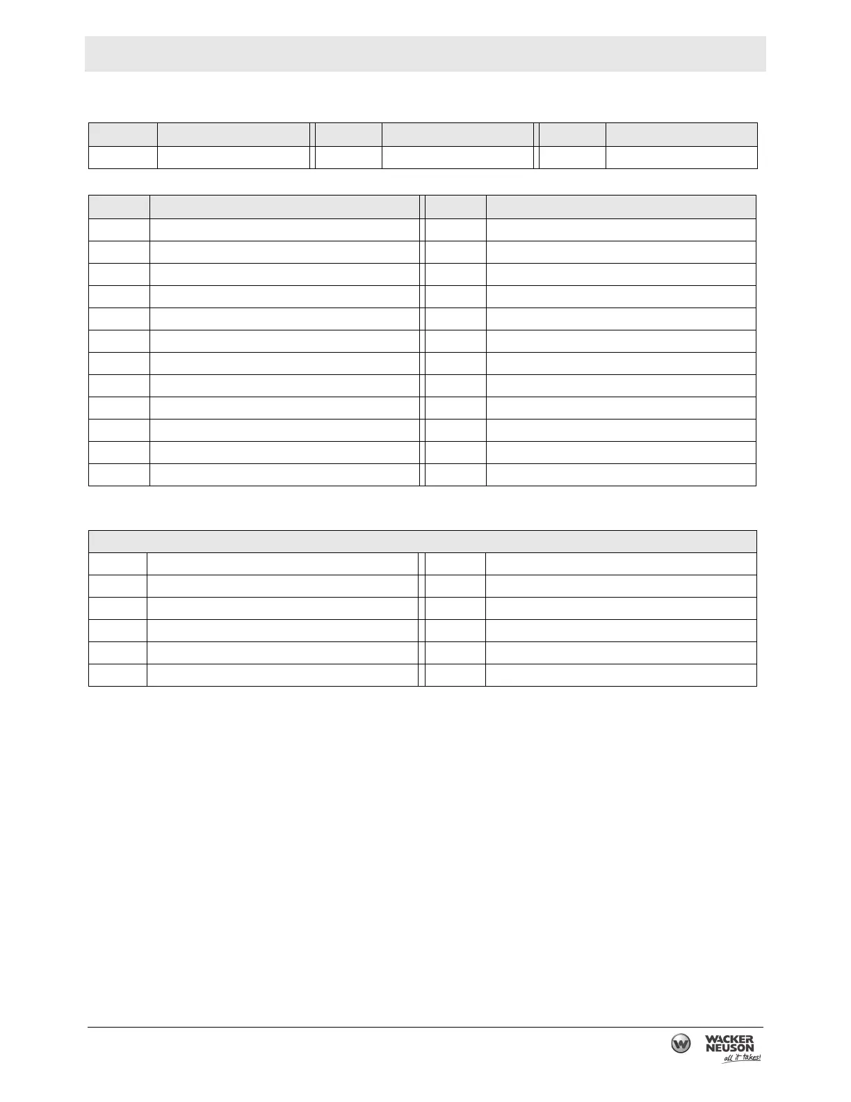
10.6 Electrical Schematic Components
Ref.
Description Ref. Description Ref. Description
A Generator B Control Box C Engine
Ref.
Description Ref. Description
1 Rotor winding 13 Secondary winding
2 Slip ring 14 Auxiliary winding
3 Main Stator 15 DC rectifier
4 Auto idle unit 16 Ground terminal
5 Voltage selector switch 17 Auto idle switch
6 Main circuit breaker 18 Earth terminal
7 Twist lock receptacle, 125/250V-30A 19 Engine ON-OFF switch
8 Circuit protector, 20A 20 Oil level switch
9 Circuit protector, 30A 21 Spark plug
10 Twist lock receptacle, 125V-30A 22 Ignition coil
11 GFCI duplex receptacle, 125V-20A 23 Fuel stop solenoid
12 Automatic voltage regulator 24 Idle solenoid
Wire colors
B Black BR Brown
Y Yellow O Orange
L Blue SB Light Blue
G Green LG Light Green
R Red P Pink
W White GR Gray