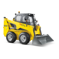
TRACK TENSION CONTROLS AND ADJUSTMENT
On the external sides of the track support, an opening is
placed inside which a valve, greased, is positioned to
adjust the tension of the track.
The exact tension of both tracks is essential for the
good functioning of the machine, both in driving and
working phases.
A tension too low or too high means an incorrect
functioning of the machine with sliding risks, or even
worse, serious damaging of the same tracks or parts of its
transmission: gear, trailer wheel, support rollers,
bearings, pegs, etc. From what said, the importance of a
correct track tension seems evident, which can be
obtained and maintained following the indications and
practical suggestions supplied below.
The interval of the controls is summed up in the
maintenance table; however, the controls of the new
track should be carried out daily.
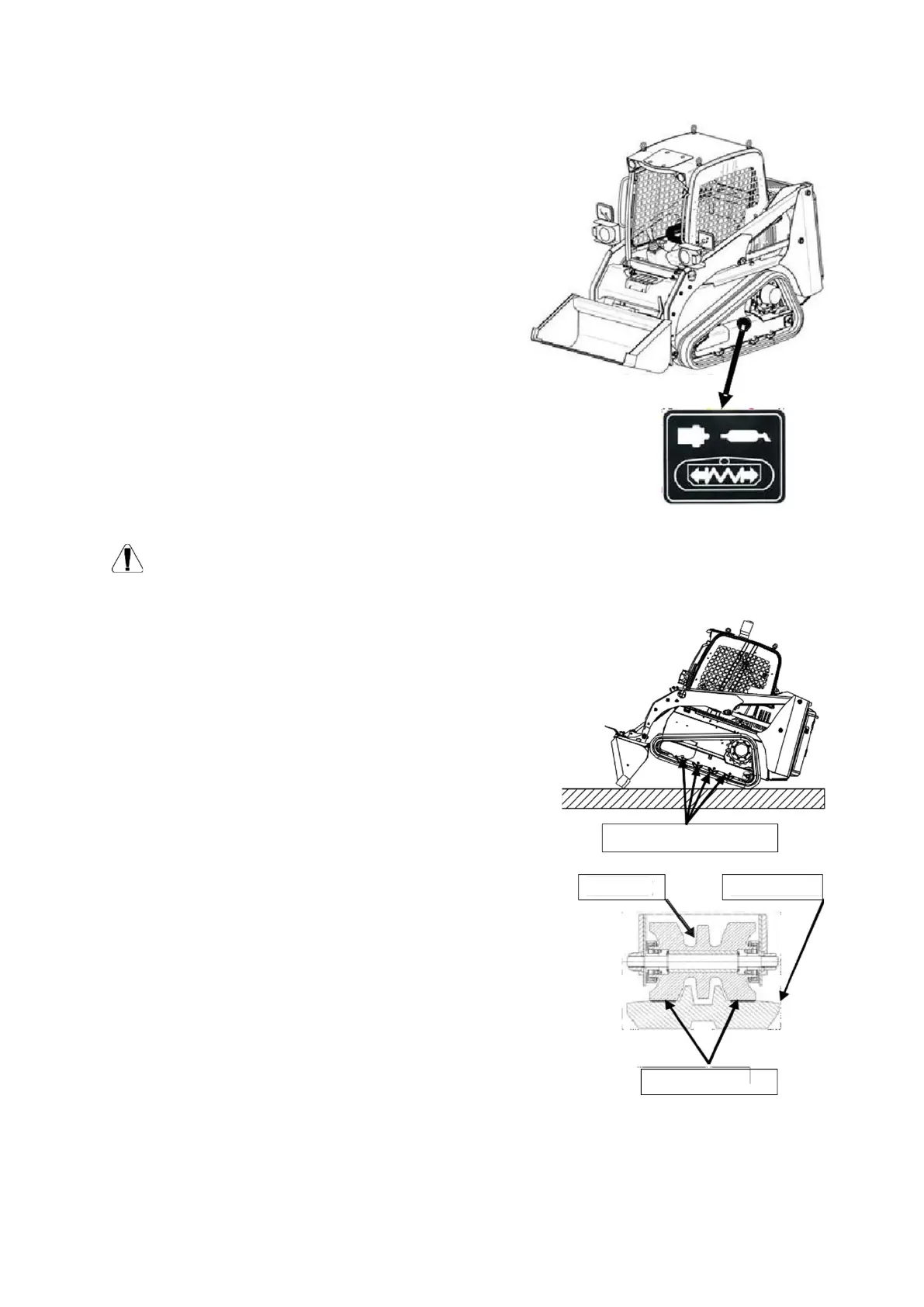
Move to a flat area, on hard and compact ground, open digger and lower it until the front part
of the machine is completely lifted; only the extremity of the digger and the rear trailer wheel of the
track must remain in contact with the ground.
For the correct tensioning, verify that the internal lower
part of the track perfectly adheres to all 4 support rollers.
If not, restore the correct tension by acting as illustrated
below.
To restore the suggested value, pump grease on to the
adjusting valve using the appropriate head on the
machine. Stop when adjustment is completed. Before
proceeding, inspection of the track and various trans-
mission organs is suggested, removing dirt and debris
eventually deposited between the track and the driving
wheel, trailer wheel and support rollers in that they
might alter the tension adjustment.
Pay particular attention during the head connecting
phase, in that the grease contained in the track tension
cylinder and blocked by the valve, may be violently
expelled with the connected risks.
The valve may be removed only by the Assistance
Service personnel.
ROLLER N. 1 - 2 - 3 - 4
WITHCONTACT
Page 45 of 61
Item – Rev(s): 8009641121– 101
TRACKROLLER
 Loading...