BA 34603_04 US – Edition 2.1 * 34603_04b110.fm 1-13
Introduction
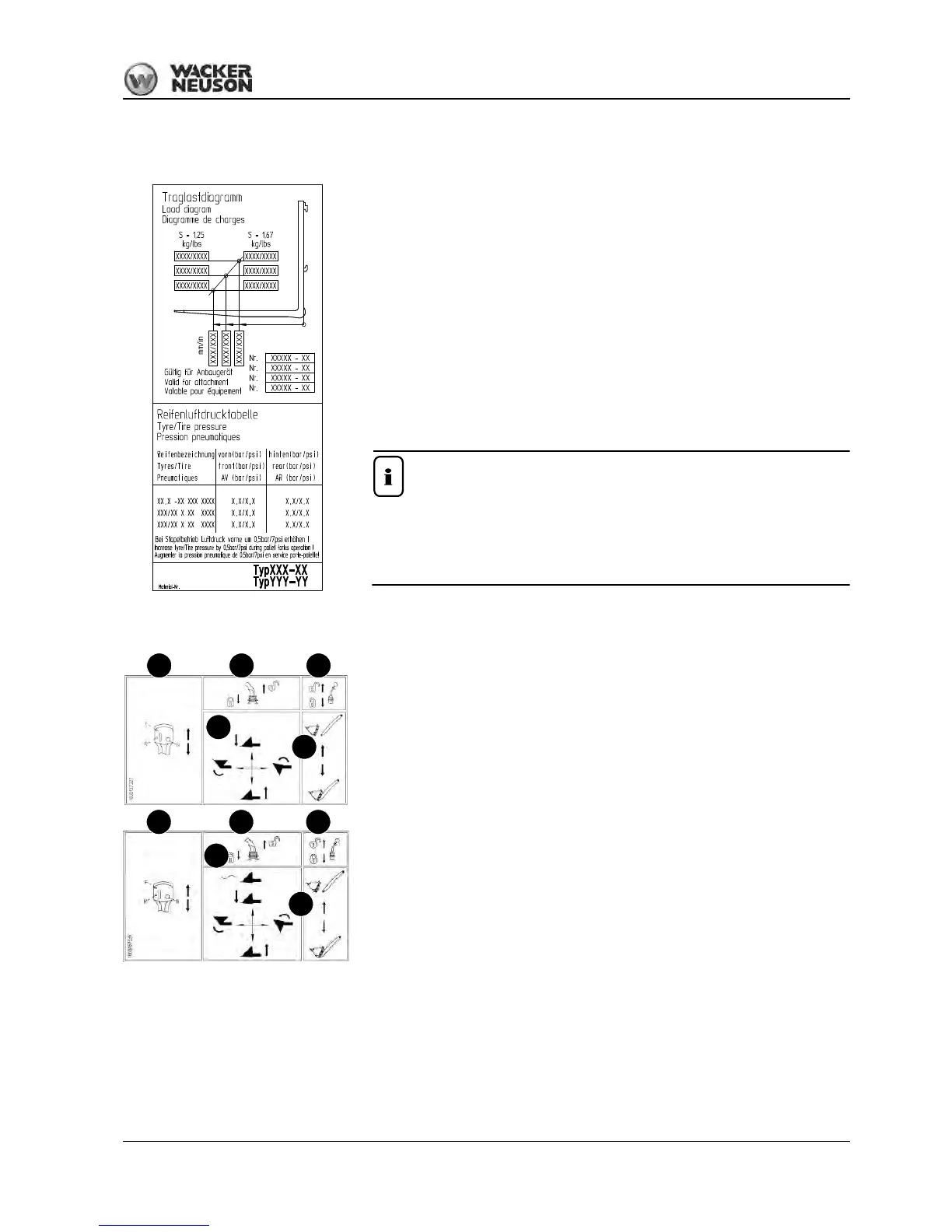
Labels inside the cab
Description (example)
... when using pallet forks with fork arms:
The framed numbers indicate the maximum authorized load on the fork arms for industrial
and off-road applications respectively. The maximum load varies according to the distance
from the load center.
Example:
• Off-road operation
➝ S = 1.67 (safety factor)
➥Load distance = 500 mm (19.68”)
• The maximum load amounts to e.g. 465 kg (1025.15 lb)!
Tire pressure table
List of authorized types of tires with prescribed tire inflation pressures.
Other information – see chapter 6 “Tires” on page 6-8
Location
Inside the cab, on left side of front window
The load diagram is valid only for applications with certified pallet forks.
• – see Attachments on page 1-5
• Observe the specific load diagrams of other attachments used, e.g. rotary
crane jib!
Description
Control lever elements (joystick)
• A = traveling direction: (F) forward/(R) reverse and (N) neutral position
• B = control lever (joystick) unlocked/locked for road travel
• C = control lever (3rd control circuit for attachments) unlocked/locked
• D = loader unit operation: raise, lower, curl and dump
• E = 3rd control circuit operation. Pick up/set down attachment
• F = loader unit operation: raise, lower with float position, curl and dump
Location
On the lower right on the side window
Fig. 16: Label: control lever operation (overview)
A
D
B C
E
F
E
A B C
 Loading...