Do you have a question about the WAGO 787-1668/0000-0080 and is the answer not in the manual?
| Tripping Characteristic | C |
|---|---|
| Width | 17.5 mm |
| Type | Miniature Circuit Breaker (MCB) |
| Voltage Rating | 230/400V AC |
| Mounting Type | DIN Rail |
| Rated Operational Voltage | 230/400V AC |
| Number of Poles | 1P |
Legal notice regarding usage rights and intellectual property of the manual.
Explains warning and informational symbols used for safety and clarity.
Defines conventions for numerical representations (decimal, hex, binary).
Clarifies the meaning of different text formatting styles used in the document.
Covers crucial legal and qualification requirements for device use and modifications.
Outlines essential safety measures for device installation and operation.
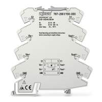
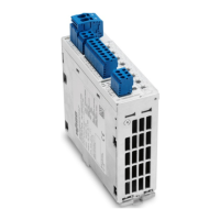
Visual overview of the device with key components identified.
Details physical interfaces for power supply and communication.
Explains the multi-colored LED indicators and their operating status meanings.
Describes the function of physical control elements like buttons and rotary switches.
Lists comprehensive technical specifications and parameters for the device.
Lists official certifications and compliance marks granted for the device.
Specifies applicable industry standards and directives the device complies with.
General statement about the device's mounting design on a DIN 35 rail.
Step-by-step guide for physically installing the device onto a DIN rail.
Instructions for safe removal of the device from its DIN rail mounting.
Illustrates a typical wiring example for connecting the electronic circuit breaker.
Explains protection mechanisms against voltage fluctuations.
Graphically shows device behavior under overcurrent conditions.
Discusses handling high capacitive loads and power requirements.
Describes device states, LED colors, and button actions.
Details the sequential activation logic for device channels.
Explains specific functions assigned to channel 8.
How to exchange real-time data via the IO-Link interface.
How to access specific device parameters and settings via acyclic communication.
Using the IODD file for device configuration and integration.