1. 2
3. 4
5
6
7
8
9
10
11
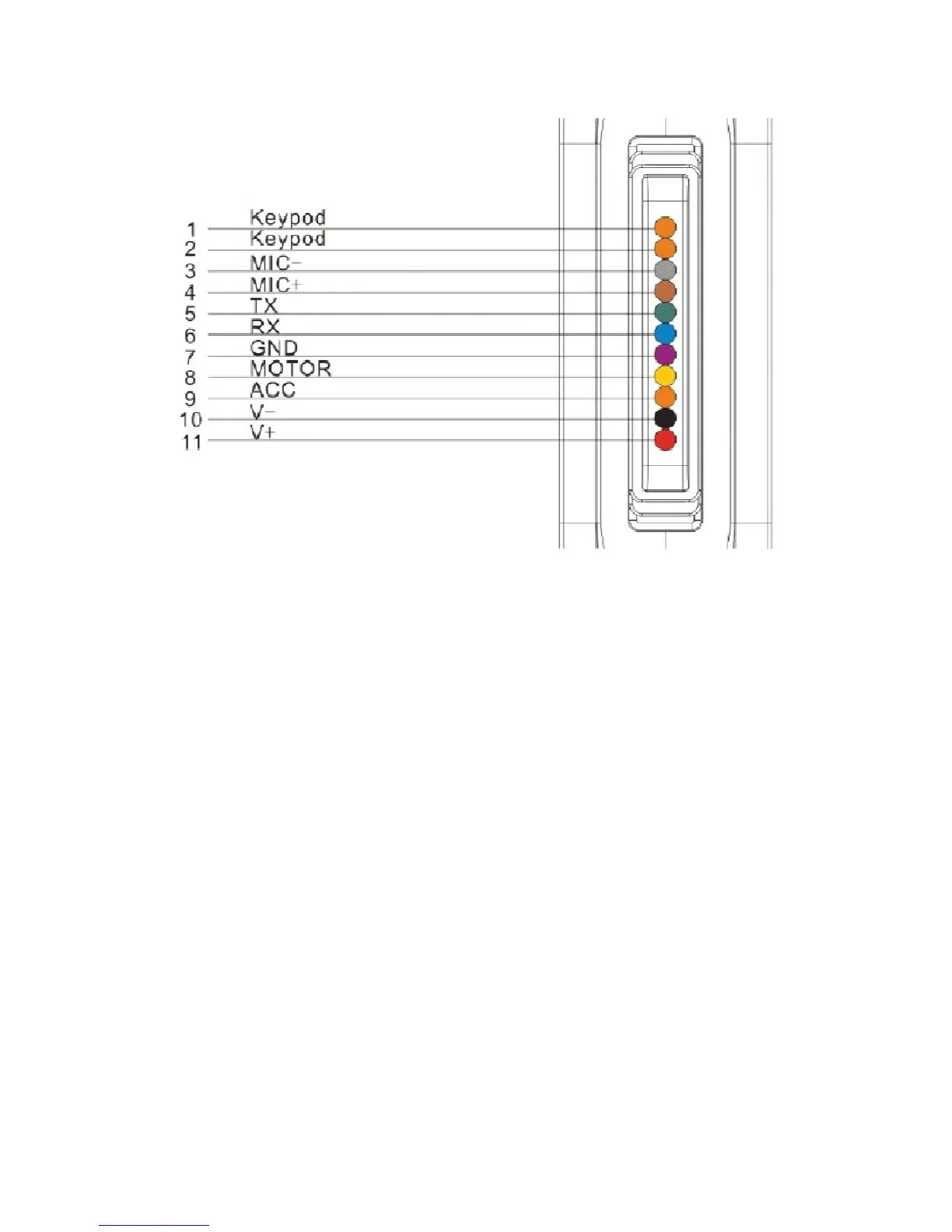
Keypod
MIC-,MIC+
TX
RX
GND
MOTOR
ACC
V-
V+
Orange/ orange
Grey/Brown
Green
Blue
Purple
Yellow
Orange
Black
Red
Connect to SOS button
Connect to Microphone
Sending data (TX)/backup
Receiving data (RX)/backup
Ground wire
Connect to relay control line
Connect to ACC ignition
Vehicle 12V/24V negative storage battery
Vehicle 12V/24V positive storage battery
Notes of the relay wiring
The relay wiring of pump: oil connectors of both ends are a fine white line (85)
and a fine yellow line (86). The fine white line (85) is connected to vehicle
positive power (+12V). The fine yellow line is connected to the device relay
control line.
Cut off the positive connection line of the pump; then connect in series to the
relay N.C. contact (thick green line 87a) and the other end to relay COM
contact (thick green line 30).
Note: The standard relay is 12V and only suits the 12V car battery. Please
choose 24V relay if it is 24V car battery.