5
P202
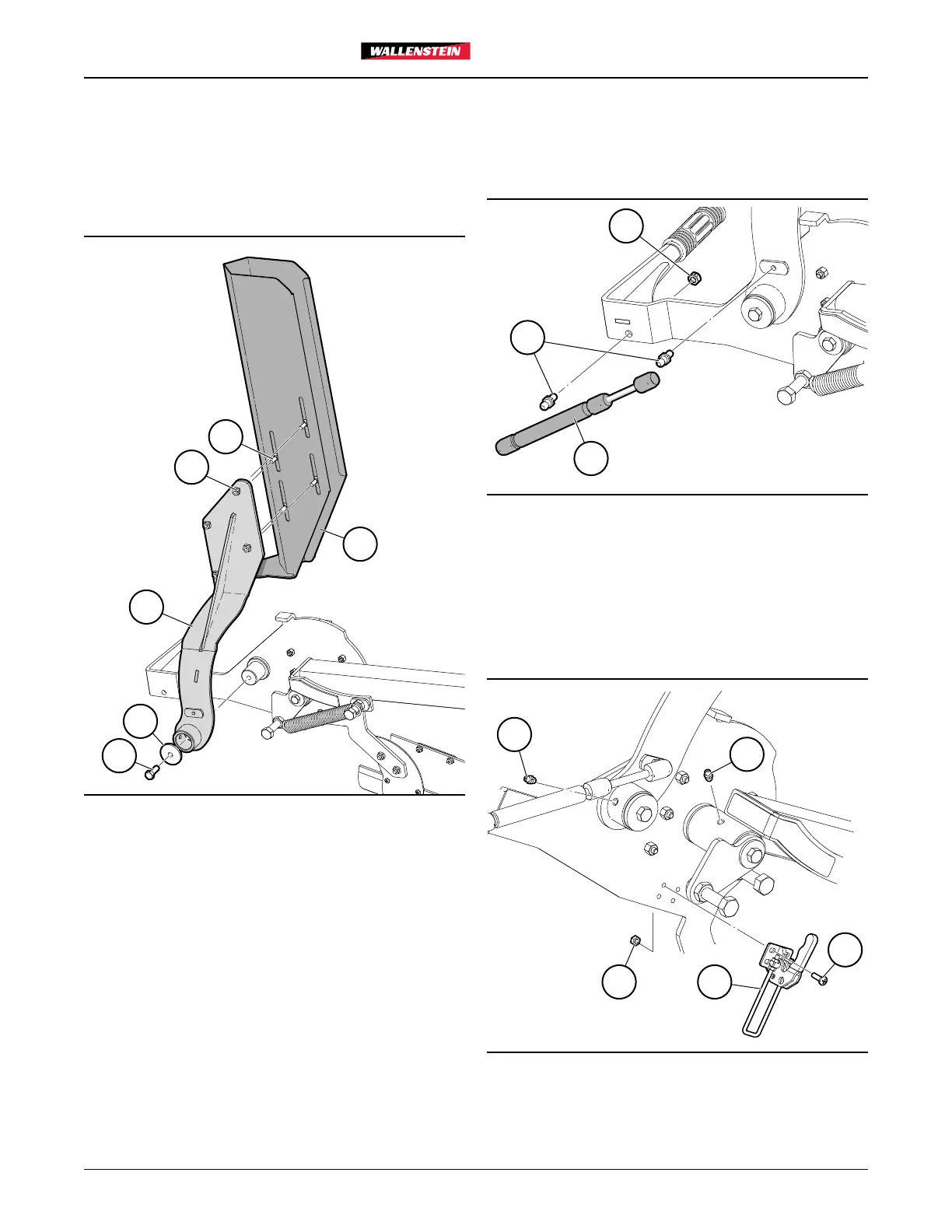
Step 4
• Fasten Chain Saw Guard (4) to Guard Spine (6) with four
1/4"NC x 3/4" Carriage Bolts (31) and 1/4" Flange Locknuts
(32).
• Slide this assembly onto the shorter shaft on the Chain
Saw Pivot. Secure to the shaft with 3/8"NC x 1" Hex Bolt
(37) and Washer (36).
4
31
32
6
36
37
Fig. 4 – Chain Saw Guard
Step 5
• Install Ball Studs (33) on the Chain Saw Pivot. The Ball
Stud in the Guard arm threads in. The one on the base end
requires 5/16"NC Lock Nut (35).
• Slide the ends of the Gas Spring (34) over the ball studs.
35
33
34
Fig. 5 – Gas Spring
Step 6
• Install the two grease fittings (30) at the two pivot points.
• Install Adjustable Draw Latch (25) on the Chain Saw Pivot
with four #10NF x 5/8" Machine Screws (26) and #10NF
Hex Locknuts (27).
30
30
26
2527
Fig. 6 – Draw Latch