Householder Information
IMPORTANT!
Your boiler must be commissioned in order to:
- Validate your warranty
- Ensure the boiler has been installed correctly and avoid premature failure
- Set the boiler to its optimum efficiency. Operating conditions for the boiler will vary from site to site, your
commissioning engineer has specialised equipment to check the oil pressure and analyse the exhaust gases for
temperature, smoke and carbon dioxide content.
Your installer will organise the commissioning of your boiler. Should you experience any difficulty locating an
engineer, our service department may be able to provide you with details of an engineer in your area.
“Benchmark” Installation, Commissioning and Service Record Log Book
Please ensure that your installer has completed all sections of the log book (found at the back of this manual).
The log book will be required in the event of any warranty work. Ensure that the service record is completed.
Warranty
Your HRM boiler is under warranty for 2 years from the date of installation.
Warranty Conditions
- The boiler must be installed and commissioned in accordance with our handbook
- The boiler must not be repaired, modified or tampered with by any person not authorised by HRM
Extended Warranty
The “Benchmark” and warranty registration document at the end of this manual should be completed as
appropriate by your installer / engineer. This is your record that the boiler has been correctly installed in accordance
with our recommendations. Return the warranty registration document to HRM in order to qualify for a further 3 year
warranty of the heat exchanger – a total of 5 years.
Extended Warranty Conditions
- The boiler must be serviced annually and maintained in accordance with this handbook. The
“Benchmark” service log is located at the back of this manual
- This warranty is in addition to your statutory and other legal rights
After Sales Service
- If your boiler fails during the warranty period contact your installer, who will be able to identify the
cause of the problem. If appropriate, your installer will contact us.
- Under no circumstances should “in warranty” work be undertaken without authorisation from the HRM
service department
- If you are unable to contact your installer please contact our service department. Quoting your boiler’s
serial number when phoning – this can be found on the cover of this manual.
Standard X-ternal & System X-ternal
Handbook
Contents Page
DESCRIPTION PAGE
Householder Information
Warranty Registration Document End Of Manual
Warranty 3
Extended Warranty 3
After Sales Service 3
Boiler Controls: Wallstar 4
System Wallstar 5
Wallstar Combi 6-7
Burner Lockout 8
Technical Specifications
Boiler Dimensions: Wallstar 9
Boiler Dimensions: System Wallstar 10
Boiler Dimensions: Wallstar Combi 11
Technical Specifications 12
Burner Settings 13
Boiler Installation
Regulations 14
Boiler Sizing 14
Refurbishing An Old System 14
System Protection 14
Boiler Location 15
Wall Construction 15
Flue Terminating Positions 16
Fuel Supply System 17
Oil Supply 17
Installation Procedure
Wallstar 18-23
System Wallstar 24-31
Wallstar Combi 32-40
Condensate Drain 41
Wiring Diagrams
Wallstar 42
System Wallstar 42
Wallstar Combi 43
Boiler Maintenance
Baffle Removal 44
Fault Diagnosis
Wallstar Combi 45
Wallstar Combi Components 46
Contacts
Tel No: 01953 455400
Fax No: 01953 454483
Email: info@hrmboilers.co.uk or technical@hrmboilers.co.uk
1
Standard Wallstar, System Wallstar &
Wallstar Combi Manual
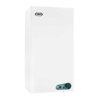
Flue Terminating Positions
Information taken from BS 5410-1:1997 and The Building Regulations: Approved Document J
Notes:
1 - Terminals should be positioned so as to avoid products of combustion accumulating in stagnant pockets around
the building or entering into buildings.
2 - Where a flue is terminated less than 600mm away from a projection above it and the projection consists of plastics
or has a combustible or painted surface, then a shield of at least 750mm should be fitted to protect these surfaces.
3 - If the lowest part of the terminal is less than 2m above the ground, balcony, flat roof or other place to which any
person has access, the terminal should be protected by a guard.
4 - Where a flue terminates near the boundry of an adjoining property, consideration should be given to possible noise
disturbance as some people are sensitive to even low noise levels.
5 - Boilers can produce sulphur deposits, occasionally these deposits are discharged out of the flue, this should be
taken into consideration when planning to site flues over patios etc.
Position Description Dimension
A Directly Below An Opening (Air Brick, Window, etc)
600mm
B Horizontally To An Opening
600mm
C Below a Gutter, Eaves or Balcony With Protection (Note 2)
75mm
D Below a Gutter, Eaves or Balcony Without Protection
600mm
E From Vertical Sanitary Pipework
300mm
F From An Internal or External Corner
300mm
G Above Ground or Balcony Level
300mm
H From Surface or Boundry Facing The Terminal
600mm
J From a Terminal Facing a Terminal
1200mm
K Vertical From a Terminal On The Same Wall
1500mm
L Horizontally From A Terminal On The Same Wall
750mm
M From An Oil Tank
1800mm
16
Standard Wallstar, System Wallstar &
Wallstar Combi Manual
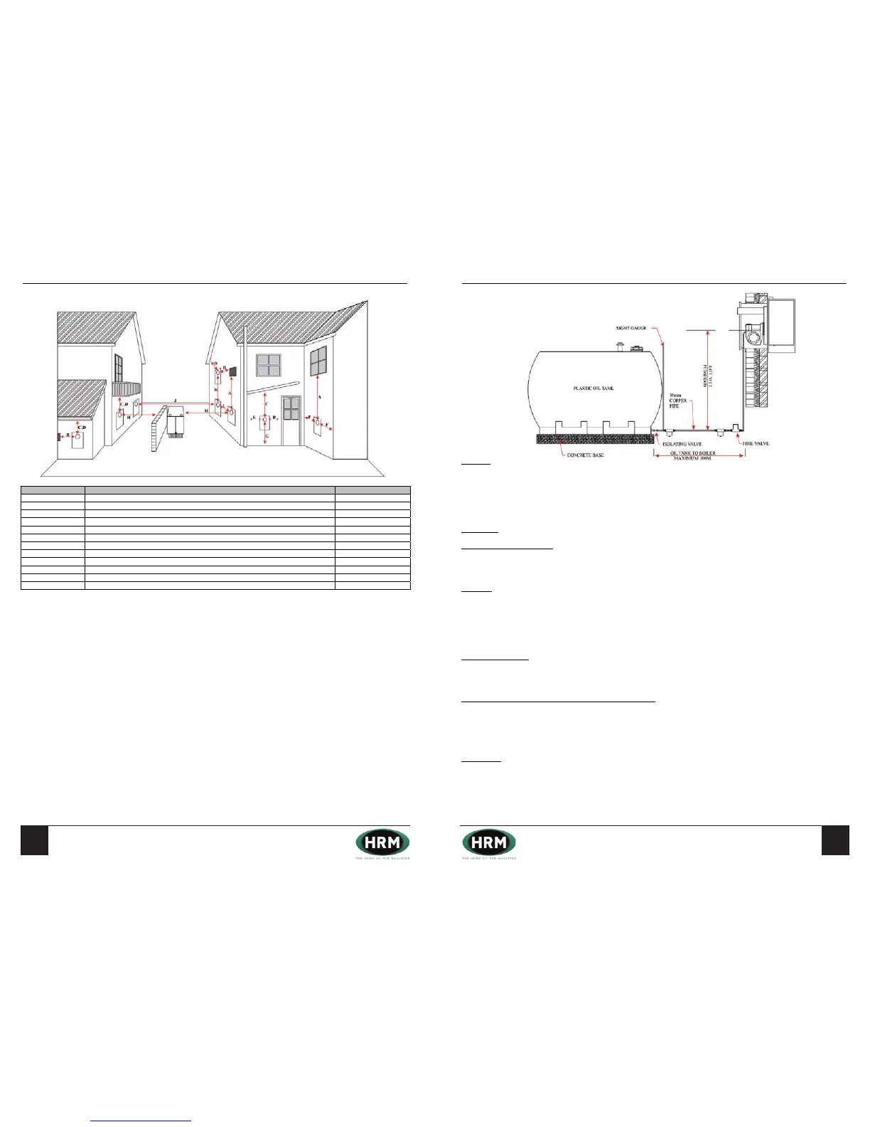
Fuel Supply System
Oil Tank
We recommend the use of plastic oil tanks, they require less maintenance than steel tanks and are longer lasting.
A bunded oil tank may be required on any environmentally sensitive site where spillage of oil could pollute rivers,
ponds, or any other water courses. Please refer to the appropriate requirements when locating oil tanks: “Control of
Pollution Regulations”, “Building Regulations” and OFTEC Technical Paper T19.
Oil Supply
Fuel Tank Below the Burner
The fuel pump can lift fuel to a height of 2.5m. A two pipe system or deaerator (Tiger Loop, 3K or similar) is not
required. For heights above 2.5m, please consult our technical department.
Pipework
Soldered fittings should not be used, as the joints will fail in the event of a fire. Flux deposits may damage the pump
and fuel may deteriorate the solder within the joint. Galvanised pipes and fittings must not be used. The aggressive
action of the fuel will erode the zinc and damage the fuel pump.
Keep the number of pipe joints to a minimum, form bends rather than using compression fittings.
Jointing Compounds
Jointing compounds should be used with care. Excessive amounts can cause blockages, and fragments may cause
failure of the fuel pump or the non-return valve. We recommend the use of a non-setting liquid pipe sealant.
Automatic Isolation of the Fuel Supply in the Event of a Fire
In accordance with Document J of the Building Regulations, we provide “a means of automatic isolation of
the fuel supply” in the form of a remote acting fire valve which must be fitted inline of the fuel supply in
accordance with BS 5410-1:1997. A clip is provided in the top of the wall duct for the fire valve capillary
bulb.
Oil Filtration
All boilers are supplied with flexible fuel lines with in line filter included. If the flexible fuel line needs replacing it must
be replaced by an item of this type (Part Number: BS099). A paper element filter is also supplied and must be fitted
adjacent to the boiler, replacement filters are available (Part Number: BS076). Where a steel oil tank is installed we
recommend a further paper element filter is also fitted adjacent to the oil tank.
17
Standard Wallstar, System Wallstar &
Wallstar Combi Manual
In accordance with Document J of the Building Regulations, “a means of automatic isolation of
the fuel supply” in the form of a remote acting re valve must be tted inline of the fuel supply in
accordance with BS 5410-1:1997. A clip is provided in the top of the wall duct for the re valve capillary
bulb.
All boilers are supplied with exible fuel line. If the exible fuel line needs replacing it must be replaced by an item of this
type (Part Number: BS012). A paper element lter is also supplied and must be tted adjacent to the boiler, replacement
lters are available (Part Number: BS076). Where a steel oil tank is installed we recommend a further paper element
lter is also tted adjacent to the oil tank.
 Loading...