Do you have a question about the Walther prazision 91489 and is the answer not in the manual?
Potential hazards from incorrect use, selection, or maintenance.
Key duties for safe operation, including instruction availability and personnel training.
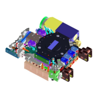
Overview of the mechanic, electric, pneumatic, and hydraulic interface.
Modular design, compact construction, and locking mechanism features.
Permitted applications and conditions for operation according to EC guidelines.
Identifies incorrect usage and operational restrictions.
Physical attributes including overall height and individual component weights.
Details on connecting/disconnecting times and speed.
Air pressure requirements and maximum carrying force.
Accuracy specifications for axis movements.
Recommended cycles for preventive maintenance.
Description of compressed air and cooling water elements.
Specifications for welding current, control current, and combined plug applications.
Identification of basic modules for robot and tool sides.
Details on limit switches, proximity switches, and press switches.
Procedures for mounting, dismounting the tool changer from the robot flange.
Steps for attaching the tool changer to the tool flange.
Connecting pneumatic elements and locking cylinders.
Procedures for installing cooling water elements.
Connecting sensors, actuators, and control elements.
Procedures for adjusting docking and locking controls.
Steps for installing signal, welding current, and combined plugs.
Notes on correct usage and EC machinery guidelines compliance.
Explanation of push-pull and pull-in techniques.
Safety and procedures for adjusting and programming the robot.
Guidelines for using gravity parking stations.
Key requirements for ensuring consistent and safe operation.
Safety precautions during commissioning, operation, and maintenance.
Procedures for regular inspection of mechanics, controls, and fluidic/electro elements.
Recommended maintenance intervals and lubrication steps.
Safety measures when dealing with malfunctions or damages.
Steps for diagnosing faults and assessing damage.
Procedures for safely separating tool changer halves in emergencies.
Steps for disassembling and repairing fluidic and electro components.
Drawings and parts lists for various tool changer components and modules.
Diagrams illustrating electrical and pneumatic connections and operational flows.
Drawings detailing mechanical interfaces and flanges for different tool changer versions.
Information on additional equipment like optical fibres and their installation.
Details on third-party components used in the system, including assembly instructions.
| Brand | Walther prazision |
|---|---|
| Model | 91489 |
| Category | Industrial Equipment |
| Language | English |