04.12
VAL.120.--.M.4L
2
OPERATION AND MAINTENANCE
BETRIEBS- UND WARTUNGSANLEITUNG
UTILISATION ET ENTRETIEN
USO E MANUTENZIONE
-
-
-
-
VCP
Series R03
SMONTAGGIO DELLA VALVOLA
DALL’ANELLO SOTTOVALVOLA
- Rimuovere i dadi di ssaggio
dellaangia.
SMONTAGGIO DELLE MOLLE E
DELLE MEMBRANE
1.Svitare i dadi ciechi di solle-
vamento e rimuovere il co-
perchio.
2.Svitareidadipostinellaparte
superioredelletrebarrelet-
tate esterne.
3. Rimuovere nell’ordine: rondelle
diguida,sofettiemolle(per
l’eventuale sostituzione delle
molle stesse).
4.Slareleduemembranedalle
trebarrelettateesterne(per
l’eventuale sostituzione delle
stesse).
5. Svitare i dadi posti sulla parte
superiore della vite centrale e
rimuovere nell’ordine: rondella
diguida,sofettoemollacen-
trale (per sostituzione di molla
e/o membrana centrale).
RIMONTAGGIO
Seguire in base al tipo di intervento
effettuato le operazioni citate prece-
dentemente nell’ordine
inverso prestando particolare at-
tenzione a:
1. Posizionare correttamente le
membrane assicurandosi che
le guarnizioni delle stesse
aderiscano al relativo piano di
appoggio.
2.Collocarelemolleelerondelle
di guida al centro delle barre
lettatediregolazione.
3. Serrare i dadi sulle viti di re-
golazione in modo corretto
arrivando fino a fine filetto.
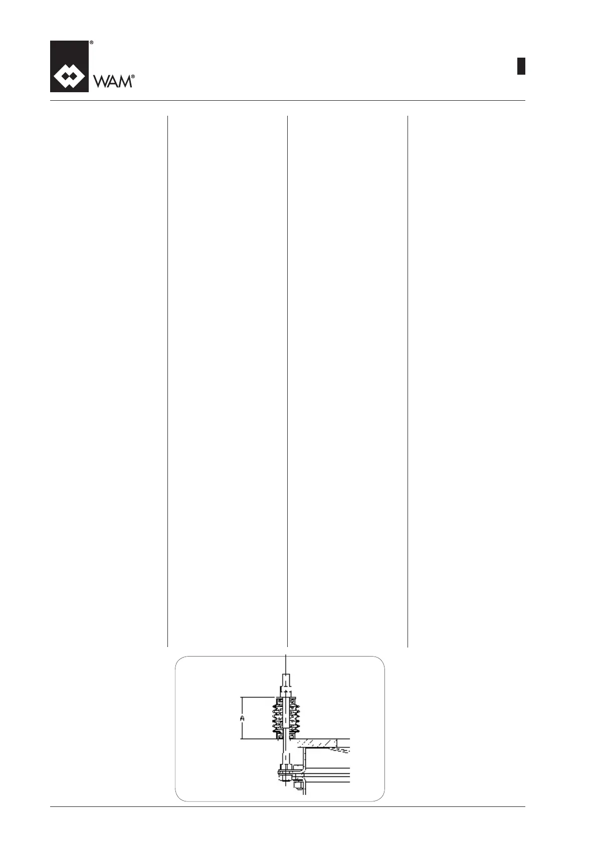
L’altezza nale fra piattello e
rondella(A,vedigura)deve
esseredicirca67±4mmper
lataglia273edicirca104±8
mm per la taglia 375.
4.Montareilcoperchiorimettendo
le rondelle in gomma nella
corretta posizione onde evitare
inltrazionidiacqua.
5. Serrare correttamente i dadi
ciechi di sollevamento.
26
DISASSEMBLY OF THE VALVE
FROM THE CONNECTOR SPOUT
-Removetheangexingnuts
DISMANTLING OF SPRINGS
AND DIAPHRAGMS
1. Unscrewcapnutsandremove
cover.
2. Unscrewupper nuts from 3
external screws.
3. Remove (in this order): spacers,
bellows and springs.
4.Slipoffthetwomembranesfrom
the three external screws.
5. Unscrew the upper nuts from
the central screw and remove
(in this order): spacer, bellows
and central spring (if replacing
the central spring and/or mem-
brane).
RE-ASSEMBLY
Depending on the type of ac-
tion carry out the operations
described earlier in reverse order
by paying special attention to:
1.Positionthediaphragmscor-
rectly ensuring that their gas-
kets adhere to the relative
supporting surface.
2. Place the springsand guide
washers at the centre of the
threaded adjustment rods.
3. Tighten the nuts on the ad-
justment screws correctly to
the end of the thread. The
nalheightbetweenplateand
washer (A, see Figure) must
be about 67 ±4 mm forsize
273andabout104±8mmfor
size 375.
4. Fit the cover after placing
the rubber washer in the cor-
rect position to prevent water
seepage.
5. Tighten the cap nuts correctly.
DEMONTAGE DES VENTILS VON
DER EINSCHWEISSZARGE
- Die Befestigungsmuttern des Flan-
sches entfernen.
DEMONTAGE VON FEDERN UND
VETILTELLER
1. HutmutternlösenundWetterhau-
be entfernen.
2. Obere3Mutternentfernen.
3. In Reihenfolge entfernen:
Führungsunterlegscheibe, Kom-
pensatoren sowie Federn zwecks
eventuellem Austausch.
4. Die2Membranenzweckseventu-
ellem Austausch von den außen-
liegenden 3 Schrauben abziehen.
5. Muttern von der mittigen Schrau-
be entfernen und in Reihenfolge
entfernen: Führungsunterleg-
scheibe, Kompensator und zen-
trale Feder und/oder zentrale
Membran zum eventuellen Aus-
tausch.
ZUSAMMENBAU
JenachdemTypdesausgeführten
Eingriffs die vorstehend beschriebe-
nen Vorgänge in der umgekehrten
Reihenfolge ausführen, wobei be-
sonders auf folgendes zu achten ist:
1.DieMembranenkorrektanordnen,
wobei sicherzustellen ist, dass
die Dichtungen derselben an der
Auageächeanhaften.
2.DieFedernunddieFührungsschei-
ben in der Mitte der regelnden
Gewindestangen anordnen.
3. Die Muttern auf den Stellschrau-
ben korrekt anziehen, d.h. bis
zum Ende des Gewindes. Die
Endhöhe zwischen der Platte und
der Unterlegscheibe (A, siehe Ab-
bildung) muss für die Baugröße
273circa67±4mmundfürdie
Baugröße375circa104±8mm
betragen.
4. Den Deckel montieren und die
Gummischeiben wieder in der
korrekten Position einlegen, damit
Wasserinltrationenvermieden
werden.
5. Die Hutmuttern korrekt anziehen.
DEMONTAGE DE LA SOUPAPE
DE L’ANNEAU DE RACCORDE-
MENT
-Enleverlesécrousdexationde
la bride.
DEMONTAGE DES RESSORTS ET
DES MEMBRANES
1. Devisserlesécrousborgneset
enlever le couvercle.
2. Dévisserles 3 écrous supé-
rieurs.
3. Enlever dans l’ordre: rondelle
de guide, soufets et ressorts
(pour l’éventuelle substitution
des ressorts-mêmes).
4.Délerles2membranesdes3
bo ulons extérieurs (pour l’éven-
tuelle substitution des mem-
branes-mêmes).
5. Dévisser les écrous sur la partie
supérieure de la vis centrale e
enlever dans l’ordre: rondelle de
guide,soufetetressortcentral
(pour substitution du ressort et /
ou de la membrane centrale.
REMONTAGE
Suivre les instructions précédentes
dans le sens inverse en faisant
particulièrement attention à:
1.Positionner correctement les
membranes en s’assurant que
leurs garnitures adhèrent au plan
d’appui respectif.
2.Placerlesressortsetlesrondelles
de guidage au centre des axes
letésderégulation.
3. Serrer les écrous sur les vis de
régulation de manière correcte
enarrivantjusqu’àlandulet.
Lahauteurnaleentreleplateau
etlarondelle(A,voirgure)doit
êtred’environ67± 4mmpour
lataille273etd’environ104±8
mm pour la taille 375.
4.Monterlecouvercleenremettant
les rondelles en caoutchouc
dans la position correcte afin
d’éviterdesinltrationsd’eau.
5. Serrer correctement les écrous
borgnes.
 Loading...