12
G25-991-2400A
H/G-25 Service (Fluid End)
NOTE: The numbers in parentheses are the Ref. Nos. on
the illustrations in the Parts Manual.
This section explains how to disassemble and inspect all
easily-serviceable parts of the pump. Repair procedures for
the hydraulic end (oil reservoir) of the pump are included in a
later section of the manual.
CAUTION: Do not disassemble the hydraulic end unless
you are a skilled mechanic. For assistance, contact Wanner
Engineering (TEL 612-332-5681 or FAX 612-332-6937) or
the distributor in your area.
CAUTION: The four bolts (26) that screw through the back
of the housing into the cylinder casting hold the casting
over the hydraulic end of the pump. Do not remove them
except when repairing the hydraulic end.
1. Remove Manifold (7), Valve
Plate (18)
a. Remove all nuts (31) and bolts (5) around the manifold.
Do not remove the four bolts (26) that are installed
through the back of the pump housing.
b. With a 3/8-in (10-mm) hex Allen wrench, remove the
centerbolt (1) and its washer (2) in the center of the
manifold.
CAUTION: Do not turn the pump drive shaft while
the manifold and valve plate are off the pump,
except when removing diaphragms or repriming the
hydraulic cells.
c. Remove the manifold (7) and support plate (43). (Support
plate (43) is used only with non-metallic pump head.)
d. Inspect the manifold for warping or wear around the
inlet and outlet ports. If wear is excessive, replace the
manifold.
To check if the manifold is warped, remove the O-rings
and place a straightedge across it. A warped manifold
should be replaced.
e. Remove the three socket-head cap screws (39) with a
3/16-in. (5-mm) hex Allen wrench.
f. Inspect the valve plate in the same manner as the
manifold.
NOTE: Plastic valve plates and manifolds should also
be inspected for cracks, and replaced if necessary.
2. Inspect Valves (11-16, 38)
The three inlet and three outlet valve assemblies in the pump
are identical (but face in opposite directions). Inspect each
valve as follows:
a. Check the spring retainer (16), and replace if worn.
b. Check the valve spring (14). If it is shorter than a new
spring, replace it (don’t just stretch the old spring).
c.
Check the valve poppet (13). If worn excessively, replace
it.
NOTE: If your pump has plastic spring retainers,
there is a tetra seal (flat O-ring, 15) between the
retainer (16) and valve seat (12).
d. Remove the valve seat (12). A seat remover is included in
the Wanner Tool Kit. On cast iron valve plates, be careful
not to break the metal ridge around the O-ring groove.
Inspect the valve seat for wear, and replace it if necessary.
Install a new O-ring (11).
e. Reinstall the valve assemblies:
• Clean the valve ports and shoulders with emery cloth,
and lubricate them with lubricating gel or petroleum
jelly.
• Install the O-ring (11) on the valve seat (12).
NOTE: Some pumps use plastic dampening
washers (38) between the valve seat (12) and
the manifold (7) or valve plate (18). Refer to the
illustrations on page 11, and the fluid-end exploded
views in the Parts Manual.
• Inlet (3 center valves). Insert the spring retainer (16)
into the valve plate, then insert the spring, valve, and
valve seat (14,13,12). If the pump has
plastic spring
retainers, a flat O-ring (15) goes between the retainer
and seat.
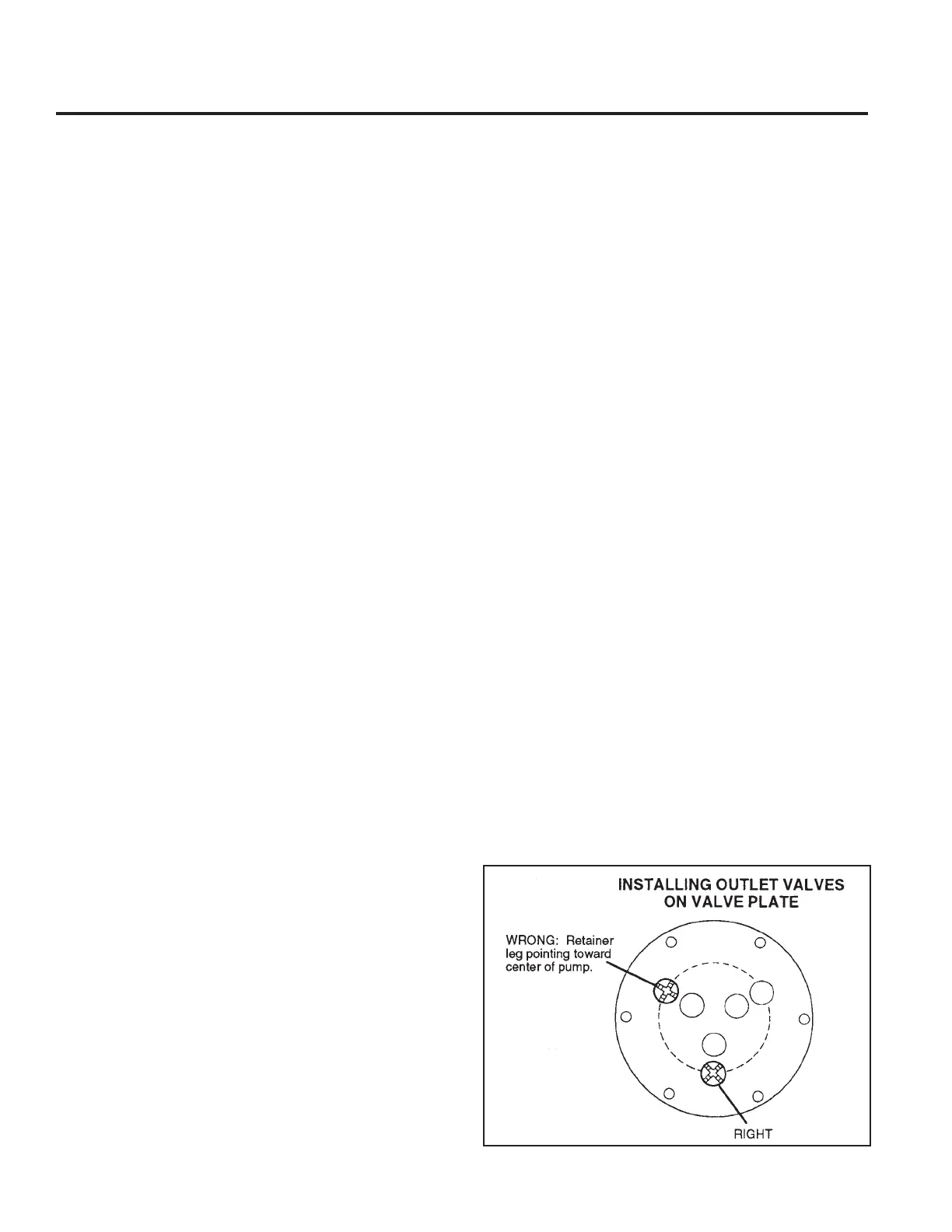
• Outlet (3 outer valves). Insert the valve seat, valve,
and spring, then the retainer. If the pump has
plastic
retainers, install the flat O-ring between the retainer
and seat. If the pump has
metal spring retainers in
the outlet valves, position them so a leg does not
point toward the center of the pump (refer to the
illustration).
 Loading...