©2013 Warn Industries, Inc. WARN® and the WARN logo are trademarks of Warn Industries Inc. 4 91853A0
INSTALLATION INSTRUCTIONS
Factory Skid Plate
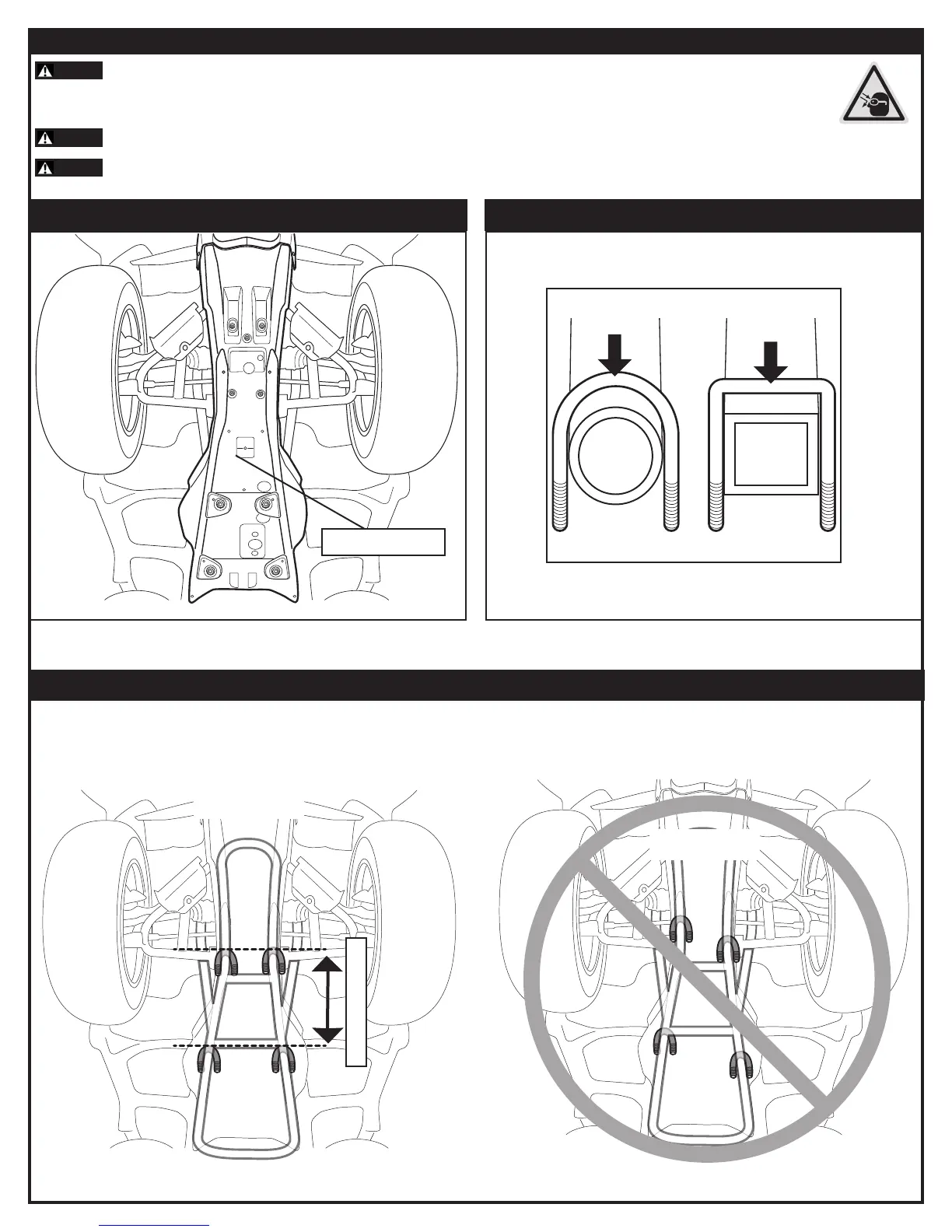
Figure 1: Locate skid plate and remove if possible.
WARNING
Always use extreme caution when drilling on any vehicle. Make sure that all fuel lines, brake lines, electrical wires, and other objects are not
punctured or damaged when/if drilling on the vehicle. Thoroughly inspect the area to be drilled (on both sides of material) prior to drilling, and relocate any
objects that may be damaged. Failure to inspect the area to be drilled may result in vehicle damage, electrical shock, re or personal injury.
WARNING
Always wear safety glasses when installing this kit. A drilling operation will cause ying metal chips. Flying chips can cause eye injury.
WARNING
Always take time to fully read and understand the installation and Operations Guide included with this product.
Figure 4: Incorrect Placement - (u-bolts not parallel and over 25” apart)
Figure 3: Correct Placement (u-bolts parallel and between 10” - 25” apart).
1. INSTALLATION 2. INSTALLATION
3. INSTALLATION
Figure 2: Determine proper u-bolt size. U-bolt type must match frame tube cross
section.
Place two u-bolts near the front end of frame (near or between front a-arms) and two u-bolts in the rear of frame (near or between foot
pegs). The front and rear sets of u-bolts should be no less than 10 inches and no more than 25 inches apart.
(4) U-bolts
Front of vehicle
U-bolts 10” - 25” apart
Front of vehicle