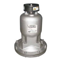
The device described in the manual is a Tranquilizer TA2 Metallic Construction Design Level 2, which is a type of automatic diaphragm-fitted surge suppressor manufactured by Warren Rupp, Inc., under the SANDPIPER brand. Its primary function is to reduce flow and pressure pulsations characteristic of reciprocating type pumps.
Function Description
The Tranquilizer operates by using a flexible diaphragm to separate a liquid chamber from compressed air chambers. A rod connected to the center of one diaphragm activates air inlet and exhaust valves, which automatically admit or exhaust air in the air chambers. This mechanism maintains the diaphragms in a mid-range of stroke, thereby providing maximum surge suppression. The unit is designed to operate in any position and should be located in the discharge piping as close as possible to the pump. The air inlet connection should be connected to a full plant air supply line before the air regulator to the pump, with a maximum pressure not exceeding 125 PSI.
Important Technical Specifications
General:
- Model: TA2 Metallic Construction, Design Level 2
- Manufacturer: Warren Rupp, Inc., a Unit of IDEX Corporation
- Certifications: CE, ISO 9001, ISO 14001, ATEX compliant (suitable for use in explosive atmospheres when properly grounded).
- Warranty: 5-year limited product warranty against defects in material and workmanship from the date of shipment.
Operating Temperatures (Material Profile):
The manual provides a comprehensive list of materials and their respective maximum and minimum operating temperatures. These limits are crucial as temperatures coupled with pressure affect the longevity of diaphragm pump components. Maximum life should not be expected at the extreme limits of these temperature ranges.
- Conductive Acetal: Max 190°F (88°C), Min -20°F (-29°C)
- EPDM: Max 280°F (138°C), Min -40°F (-40°C)
- FKM (Fluorocarbon): Max 350°F (177°C), Min -40°F (-40°C)
- Hytrel®: Max 220°F (104°C), Min -20°F (-29°C)
- Neoprene: Max 200°F (93°C), Min -10°F (-23°C)
- Nitrile: Max 190°F (88°C), Min -10°F (-23°C)
- Nylon: Max 180°F (82°C), Min 32°F (0°C)
- Polypropylene: Max 180°F (82°C), Min 32°F (0°C)
- PVDF (Polyvinylidene Fluoride): Max 250°F (121°C), Min 0°F (-18°C)
- Santoprene®: Max 275°F (135°C), Min -40°F (-40°C)
- UHMW PE: Max 180°F (82°C), Min -35°F (-37°C)
- Urethane: Max 150°F (66°C), Min 32°F (0°C)
- Virgin PTFE (PFA/TFE): Max 220°F (104°C), Min -35°F (-37°C)
Metals:
- Alloy C: Equal to ASTM494 CW-12M-1 specification for nickel and nickel alloy.
- Stainless Steel: Equal to or exceeding ASTM specification A743 CF-8M for corrosion resistant iron chromium, iron chromium nickel, and nickel-based alloy castings (commonly referred to as 316 Stainless Steel).
Temperature Ranges:
- Ambient Temperature Range: -20°C to +40°C
- Process Temperature Range:
- -20°C to +80°C for models rated as category 1 equipment
- -20°C to +100°C for models rated as category 2 equipment
- These ranges must not exceed the operating temperature range of the applied non-metallic parts.
Torque Specifications (for assembly):
- Diaphragm assembly: 480 In-lbs.
ATEX Compliance (for explosive atmospheres):
- Hazardous Location Applied (AODD Pumps and Surge Suppressors):
- II 2 G Ex h IIC T5...225°C (T2) Gb
- II 2 D Ex h IIIC T100°C...T200°C Db
- II 2 G Ex h IIB T5...225°C (T2) Gb
- II 2 D Ex h IIIB T100°C...T200°C Db
- Materials for ATEX: Metallic pump models with external aluminum components, conductive plastic pump models with integral muffler, and Tranquilizer® surge suppressors.
- EU Type Examination Certificate No.: DEKRA 18ATEX0094X (for AODD Pumps).
Food Contact Materials (EC No 1935/2004, EC No 2023/2006, EU No 10/2011):
- Materials: Rubber, Metals & Alloys, Plastics (PTFE and FKM/PTFE coated).
- Conditions for plastic components: Suitable for contact with multiple food types, provided storage contact time does not exceed 1/2 hour, contact temperature does not exceed 40°C, and maximum operating temperatures within the instructions manual are not exceeded. Regular inspections are recommended due to potential for process fluids to contact nonconforming materials if diaphragm fails.
Usage Features
Installation:
- The Tranquilizer should be installed in the discharge piping as close to the pump as possible.
- It can operate in any position.
- Connect the air inlet to the plant air supply line before the air regulator to the pump, ensuring pressure does not exceed 125 PSI.
- For optimal pump performance, keep suction line length and fittings to a minimum and do not reduce suction line diameter.
- An air supply with sufficient capacity and pressure is required. A pressure regulating valve should be installed.
Air Valve Lubrication:
- The air distribution system is designed for lube-free operation.
- If lubrication is desired, an air line lubricator can be installed to deliver one drop of SAE 10 non-detergent oil for every 20 SCFM (9.4 liters/sec.) of air consumed.
Air Line Moisture:
- Water in compressed air can cause icing/freezing of exhaust air, leading to erratic cycling or pump stoppage. A point-of-use air dryer can reduce this.
Air Inlet and Priming:
- To start, slightly open the air shut-off valve. Once primed, the air valve can be opened to increase air flow. If increased cycling rate does not increase flow, cavitation has occurred, and the valve should be closed slightly for efficient air flow to pump flow ratio.
Safety Information:
- Always read the safety warnings and instructions before installation and start-up to prevent damage and voiding warranty.
- Flush the pump after each use when handling materials that settle or solidify. Drain completely in freezing temperatures.
- Before operation, inspect and retighten all fasteners to recommended torques to prevent leakage.
- Nonmetallic pumps and plastic components are not UV stabilized and should not be exposed to UV light for extended periods.
- Always flush the pump clean before disassembly when used for toxic or aggressive fluids.
- Before maintenance, shut off compressed air, bleed pressure, and disconnect air line. Wear approved eye protection and protective clothing.
- Be aware of airborne particles and loud noise hazards; wear eye and ear protection.
- In case of diaphragm rupture, pumped material may enter the air end and discharge into the atmosphere. If hazardous/toxic, pipe the air exhaust to a safe containment area.
- Ground the pump, piping, valves, and containers to prevent static sparking, fire, or explosion, especially with flammable liquids.
- The pump is pressurized internally during operation; ensure all fasteners are in good condition and properly reinstalled.
- Hazard Warning: Avoid using 1,1,1-Trichloroethane, Methylene Chloride, or other Halogenated Hydrocarbon solvents with pressurized fluid systems having Aluminum or Galvanized wetted parts, as this can cause explosion hazards. Consult the factory for questions.
Maintenance Features
Service Instructions:
- Before servicing, ensure inlet air pressure is disconnected.
- Diaphragms are serviced by removing hex nuts or v-band and the center spool casting.
- Virgin PTFE diaphragms are placed over the "wetted" sides of elastomeric diaphragms.
- Inlet and exhaust air valves are located externally for easy access and service.
Troubleshooting Guide:
The manual includes a detailed troubleshooting guide covering various symptoms, potential causes, and recommended solutions, such as:
- Pump Cycles Once: Deadhead, incorrect air valve/gasket installation, bent/missing actuator plunger.
- Pump Will Not Operate / Cycle: Over lubrication, lack of air, blocked discharge line, blocked air exhaust muffler, cavitation, obstructed check valve, missing/damaged valve balls/seats.
- Pump Cycles Running Sluggish / Stalling, Flow Unsatisfactory: Over lubrication, icing, clogged manifolds, deadhead, cavitation, excessive suction lift, air supply issues, undersized lines, air leakage, entrained air/vapor lock.
- Product Leaking Through Exhaust: Diaphragm failure, loose diaphragm plates, excessive inlet pressure/air pressure.
- Premature Diaphragm Failure: Cavitation, excessive flooded suction pressure, chemical/physical incompatibility, incorrect diaphragm plates, worn outer plates.
- Unbalanced Cycling: Excessive suction lift, undersized suction line, pumped fluid in air exhaust muffler, suction side air leakage, obstructed check valve, worn valve/seat, entrained air/vapor lock.
Repair Parts:
The manual provides a composite repair parts drawing and a comprehensive list of parts with their descriptions and quantities, including:
- Bearings, body, cap, capscrews, chambers (inner/outer), diaphragms (various types, including PTFE overlay), tube fittings, nuts, O-rings, activator plates, diaphragm inner/outer plates (various materials), plugs, retainer rings, diaphragm/activator rods, U-cup shaft seals, valve assemblies (body, poppet, spring, O-ring), elbows, and washers.
- The use of non-OEM replacement parts will void agency certifications.
Recycling:
- Many components are recyclable. Users are encouraged to recycle worn-out parts and pumps after thoroughly flushing any hazardous pumped fluids.