4. Slide second clamp ring loosely over Hush Cushion
®
and up to previously tightened clamp ring. Do not tighten.
5. Unscrew legs until there is a space of approximately 1/4” between the top of the upper housing and the Hush Cushion
®
. Raise disposer until
the upper housing slides into the Hush Cushion
®
.
Slide the loose clamp ring between the two lower beads on the Hush Cushion
®
and tighten.
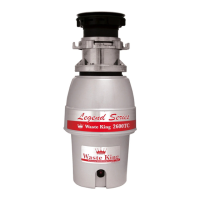
6. Assemble swirl spray or swirl sprays as shown in Figure 8. The method of assembly of the swirl sprays is typical. Other combinations of con-
vertible and fixed swirl sprays are available. The outlet hole of fixed spray head should be horizontal to promote swirling action in cone sink.
(convertible spray see Figure 9.)
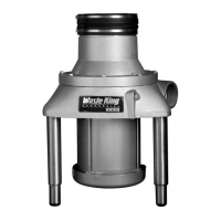
7. Connect copper tube or tubes to swirl sprays and bend in gradual curve to connect to fittings in valves. See Figure 7.
8. Thread special nipple into drain outlet, slide hush connector over pipe and assemble and tighten clamp ring in two grooves.
NOTE: ALL PLUMBING AND ELECTRICAL CONNECTIONS SHOULD BE MADE ACCORDING TO LOCAL CODES.
INSTALLATION DIMENSIONS AND DRAINLINE CONNECTIONS
FIG. 7
NOTE:
A globe valve used for metering flow to prevent solenoid
hammering must be installed between solenoid valve and
disposer. See Fig. 7. Any valve ahead of the solenoid valve
must be opened and cause no restrictions.
IMPORTANT! Do not test or run disposer without mini-
mum water flow (see Plumbing Installation) as this will
damage the seal and void the warranty.
NOTE:
Disposer assembly includes disposer, outlet, nipple, Hush
Cushion
®
, clamps and supporting legs. Other items must be
purchased separately. Items shown in gray in Figure 7 are
available in equipment groups ordered separately.
1" MIN.
SEE FIG. 11
APPROX. 40"
FIG. 8 FIG. 9 CONVERTIBLE SPRAY
AERATOR SPRAY
SPRAY GASKETS
STEEL WASHER
CONICAL –
BRASS WASHERS
NUT
LOCK
NUT
CONICAL
WASHER
TUBING
LOCK
NUT
TUBING
NUT
STEEL WASHERSPRAY HEAD
BRASS
WASHERS
SPRAY HEAD
GASKET
The convertible spray
should be located
opposite the direction
of travel of dishes in
scrapping operation.
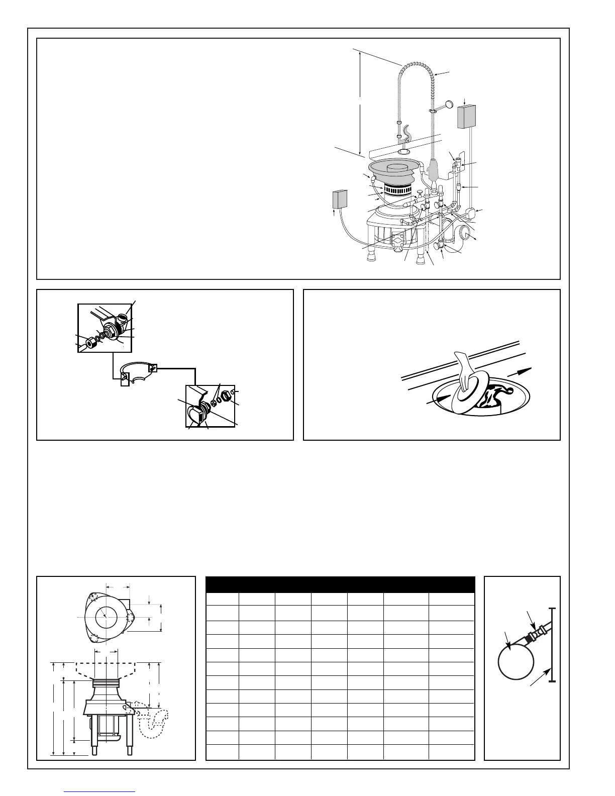
FIG. 10 FIG. 11
DIMENSIONS
2000-1 2000-3 3000-3 5000-3 5000-38 10000-3
A
32
3
/
8 - 35
1
/
8 32
3
/
8 - 35
1
/
8 32
3
/
8 - 35
1
/
8 32
7
/
8 - 35
3
/
8 32
61
/
64 - 35
29
/
64 32
61
/
64 - 35
29
/
64
B 21
5
/16 20
9
/16 22
15
/32 22
1
/2 22
37
/64 23
37
/64
C 6
5
/8 6
5
/8 6
5
/8 6
5
/8 6
5
/8 6
5
/8
D 6666 8 8
E 16
1
/4 16
1
/4 17
15
/16 17
19
/64 17
3
/8 17
3
/8
F 16 16 16
1
/8 16
5
/8 16
23
/32 16
23
/32
G
25
3
/4 - 28
1
/2 25
3
/4 - 28
1
/2 25
3
/4 - 28
1
/2 26
1
/4 - 28
3
/4 26
21
/64 - 28
53
/64 26
21
/64 - 28
53
/64
H 5
1
/8 5
1
/8 6
7
/8 8
7
/16 8
7
/16 8
7
/16
J 5
3
/4 5
3
/4 8
7
/8 88 8
K 2
5
/8 2
5
/8 3
3
/8 4
3
/4 4
3
/4 4
3
/4
L 6
7
/16 6
7
/16 7
13
/16 10
13
/16 10
13
/16 10
13
/16
*
*
TRAP
WALL
DISPOSER
If space between dis-
poser and wall is
insufficient to allow
for installation of trap,
waste line may have
to be at an angle to
the wall as shown.
J
K
H
E
F
A*
G*
B
C
G minus B
D
Water
Inlet
Drain
Slope =
1/4” Per
Foot
L
Sink
Flange
*
Legs are adjustable beyond the minimum shown in the screw adjustment. 2” clearance must be maintained beneath unit for proper ventillation.
 Loading...