Do you have a question about the WATANABE WPMZ-3 Series and is the answer not in the manual?
Specifies operating environment limits like temperature, humidity, dust, and corrosive gases.
Details on proper installation, wiring, and insulation class requirements for safe operation.
Procedures to ensure the product is installed correctly and undamaged before initial operation.
Steps to identify and address issues like strange sounds, smells, or overheating before considering a breakdown.
Guidelines for periodic checks, cleaning, and general upkeep to ensure long-term reliability.
Instructions for safely and responsibly disposing of the product as industrial waste.
Defines the duration of the product warranty, typically one year from delivery.
Outlines conditions covered and excluded by the warranty, specifying repair or replacement terms.
Clarifies the manufacturer's responsibility regarding consequential or indirect damages.
Explains how to identify and verify the product's model code against the ordered specifications.
Provides detailed physical dimensions of the product for installation planning.
Details the procedure for panel cut dimensions and securing the unit using fixing attachments.
Describes wiring for comparative outputs (OC) and external control inputs using screwless terminals.
Details connections for strain gauge inputs and GO outputs using screwless terminals.
Explains wiring for analog outputs and BCD/RS-232C/RS-485 communication.
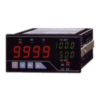
Identifies and explains the function of each physical component on the front panel.
Provides a guide to understanding the meaning of various icons displayed on the measurement and setting screens.
Describes how to navigate and use functions directly from the measurement screen.
Details the procedure for accessing and modifying various product settings via the menu system.
Explains how to switch between Default, Multi Hold, and Wave Compare measurement modes.
Step-by-step guide for calibrating strain gauge inputs, including zero and actual load adjustments.
Guide for calibrating process inputs, covering sensor power, range, offset, and full-scale adjustments.
Instructions for setting up calculations based on two input signals, including expression and coefficient.
Details on configuring analog output settings, including range, display value, and scaling.
Explains how to set up comparison outputs based on reference sources, modes, and conditions.
Advanced input settings like Analog Filter, Sampling Rate, MoveAve, and InputCorrect.
Advanced settings for 2-input calculations, including InsDispStep, DispLimit, ZeroArea, StableArea, and StableTime.
Advanced settings for comparison alarms, including ActCondition, OnDelay, OffDelay, OutputMode, OutputLogic, and OnBgColors.
Advanced settings for BCD output, covering PatternSelect, OutputDispValue, DataSignalLogic, and SyncSignalLogic.
Configuration for Modbus communication, including Slave Address, Baudrate, and Parity.
Settings for RS-232C communication, covering Protocol, Baudrate, DataLength, Parity, Stopbit, and Delimiter.
Introduces using external control terminals for functions like comparison reset, hold, and digital zero.
Explains individual external control functions such as DispHold, MaxHold, MinHold, AmpHold, DevHold, AveHold, HoldReset, DigitalZero, DispChange, TrendLog, PatternChange, WaveCompare, and MultiHold.
Details specific settings related to hold functions like DispMode, DispDelay, HoldMode, DevBaseValue, and AveHoldCount.
Explains how to register and use shortcut functions for external controls and calibration.
Step-by-step procedure for registering functions to shortcut keys for quick access.
Describes how to trigger registered shortcut functions via key presses.
Lists all functions that can be assigned to shortcut keys for easy reference.
Allows selection of measurement display formats like Ach, Bch, Calc, or combinations.
Configures the level display format for measurement values, showing them as bar graphs.
Sets up the trend display format, showing measurement values as a graph over time.
Basic system settings including Brightness, PowerOnDelay, PowerSavingTime, MeasureMode, D-ZeroRetention, and Language.
Options for initializing settings, including saving user defaults, loading defaults, or resetting to factory defaults.
Checks input signal status (percentage, actual value) and external control ON/OFF states.
Allows testing of comparison outputs, GO outputs, analog, and BCD outputs for verification.
Introduces the function for logging trend data before and after comparison alarms occur.
Details the format and capacity of logged data, including data points, logging time, and storage.
Explains the mode for comparing measurement waveforms against standard waveforms.
Describes how to create standard comparison waveforms by editing measured data.
Outlines the procedure for performing waveform comparison measurements and analyzing results.
Details how to log and save measurement waveform data, including saving OK/NG data and erasing logs.
Covers settings specific to wave comparison mode, such as PatternSelect, StartCondition, Threshold, and RefWaveCapture.
Introduces the mode for dividing measurements into sections with individual hold and comparison settings.
Explains methods for switching between measurement sections (Level, Edge, Timer, Auto).
Defines conditions for starting hold operations within each section (Normal, Threshold, DelayTimer).
Details how comparison judgement is activated, including timing, values, alarms, and output logic.
Describes different hold types like Peak, Bottom, Amplitude, Deviation, Maximal, Minimal, Difference, and Inflection.
Provides general technical specifications, including display, external controls, power, and dimensions.
Details the electrical specifications for strain gauge and process inputs, including range, accuracy, and resolution.
Covers electrical specifications for comparison outputs, analog output, BCD output, and communication interfaces.
Explains how error codes are displayed and provides a list of common errors and recovery procedures.
Lists common operational issues and their corresponding troubleshooting steps and actions.
Summarizes key functions and their operations in measurement and setting modes.
A comprehensive table mapping settings across different menu layers and their initial/settable values.
Illustrates how comparison modes (Level, Zone, Diff) behave with different output modes (Normal, Latch, OneShot).
Explains the format of saved waveform data and how to acquire it via communication.
| Brand | WATANABE |
|---|---|
| Model | WPMZ-3 Series |
| Category | Measuring Instruments |
| Language | English |