Installation Instructions
Before Installation
Inspect the Package
Open the box and take out the system housing, all the components and quick connect fittings. nspect them
according to the parts list to ensure nothing is eft out or damaged during shipping. f there are any parts
cracked or broken, please do no proceed with the installation and contact Waterdrop customer service by
hotline +1-888-352-3558 (PST) or by email: service@waterdropfi ter.com. Identify and get familiar with all
components for quick installation.
Required Tools
• Variable speed dril
• Utility knife or scissors
• Drill bit: 1/4" (for drainpipe), 1" (for faucet hole)
• Adjustable wrench, pliers
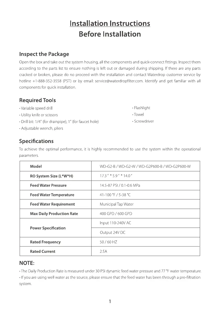
Specifications
• Flashlight
• Towel
• Screwdriver
To achieve the optimal performance, it is high y recommended to use the system within the operational
parameters.
Model
RO System Size
Feed Water Pressure
Feed Water Temperature
Feed Water Requirement
Max Daily Production Rate
Power Specification
Rated Frequency
Rated Current
NOTE:
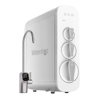
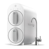
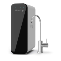
WD-G2-B / WD-G2-W / WD-G2P600 B / WD G2P600-W
. *14.0"
14.5-87 PSI / 0.1-0.6 MPa
4 -100 OF/ 5-38 0c
Municipal Tap Water
400 GPD / 600 GPD
Input IIO 240V AC
Output 24V DC
50 / 60 HZ
2.5A
•The Dai y Production Rate is measured under 30 PSIdynamic feed water pressure and 77 OFwater temperature.
• If you are using wel water as the source, please ensure that the feed water has been through a pre-filtration
system.
1