EasyManua.ls Logo

WaterFurnace AT022C/D User Manual

WaterFurnace AT022C/D
28 pages
To Next Page IconTo Next Page
Page #1 background imageLoading...
Page #1 background image
Installation
Guide
P/N 96P557A01 rev. 2/99
Geothermal System Single-Speed
Installation and Maintenance Manual
208-230/60/1 & 208-230/60/3
WARNING: Before performing service or maintenance operations on a system,
turn off main power switches to the indoor unit. If applicable, turn off the accessory heater
power switch. Electrical shock could cause personal injury.
Installing and servicing heating and air conditioning equipment can be hazardous due to
system pressure and electrical components. Only trained and qualified service personnel should
install, repair or service heating and air conditioning equipment.
Untrained personnel can perform the basic maintenance functions of cleaning coils and
cleaning and replacing filters. All other operations should be performed by trained service
personnel. When working on heating and air conditioning equipment, observe precautions in the
literature, tags and labels attached to the unit and other safety precautions that may apply.
Follow all safety codes. Wear safety glasses and work gloves. Use a quenching cloth for
brazing operations and have a fire extinguisher available.
Move units in the normal “up” orientation as indicated by the arrows on each carton. Horizon-
tal units may be moved and stored per the information on the carton. Do not stack more than
three units in total height. Vertical units may be stored one upon another to a maximum height of
two units. Do not attempt to move units while stacked. When the equipment is received, all items
should be carefully checked against the bill of lading to be sure all crates and cartons have been
received. Examine units for shipping damage, removing the units from the cartons if necessary.
Units in question should also be internally inspected. If any damage is noted, the carrier should
make the proper notation on the delivery receipt, acknowledging the damage.
Moving and
Storage
Model
Nomenclature
Table of
Contents
Model Nomenclature 1
Safety Considerations 1
Moving and Storage 1
Physical Data 2
General Installation Information 2-5
Closed Loop Cooler/Boiler Systems 5-6
Closed Loop Ground Source Systems 6-8
Open Loop Groundwater Systems 8-9
Desuperheater Connection 9-10
Initial Desuperheater Start Up 10-11
Electrical Connections 11-12
Wiring Schematics 13-16
Thermostats 17
Microprocessor Control Operation 17-19
Blower Speed 19
Blower Performance 20
Unit Start-Up 20-22
Preventive Maintenance 23
Troubleshooting 24
Replacement Procedures 24
Unit Operating Pressures 25
Unit Electrical Data 25
Safety
Considerations
Model Type
ATV= Vertical Premier Unit
ATH= Horizontal Premier Unit
Non-Standard Options
Coax Options
C = Copper
N = Cupronickel
Unit Size
034 = 34,000 BTUH Nominal cooling at
90° F entering water
Design Vintage
C or higher = Premier2
Return Air Options
L = Left return
R = Right return
For Future Use
ATV
D
034
1
1
0
C
L
T
X
Electrical Characteristics
0 = 208-230/60/1 Commercial
1 = 208-230/60/1 Residential
3 = 208-230/60/3 Commercial
Discharge Air Options
B = Bottom discharge (Vertical)
T = Top discharge (Vertical)
T = End discharge (Horizontal)
T = Side discharge (Horizontal)
Hot Water Options
0 = No hot water option
1 = Hot Water Generation w/pump
Question and Answer IconNeed help?

Do you have a question about the WaterFurnace AT022C/D and is the answer not in the manual?

WaterFurnace AT022C/D Specifications

General IconGeneral
BrandWaterFurnace
ModelAT022C/D
CategoryFurnace
LanguageEnglish

Summary

Model Nomenclature

Model Identification Codes

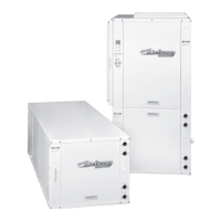
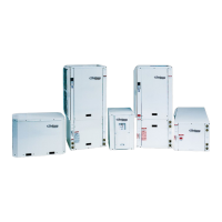
Defines unit type, size, vintage, electrical characteristics, and options.

Safety Considerations

General Safety Precautions

Emphasizes trained personnel and safety equipment for handling.

Handling and Storage Safety

Covers safe practices for moving and storing the unit.

Moving and Storage

Unit Orientation and Stacking

Specifies upright orientation and maximum stacking height.

Inspection for Shipping Damage

Advises checking for shipping damage upon receipt.

Physical Data

Fan Motor, Compressor, and Coil Specs

Details fan motor, compressor, and air coil specifications.

Refrigerant, Filter, and Weight Data

Lists refrigerant charge, filter types, and unit weights.

General Installation Information

Unit Location Requirements

Specifies environmental conditions and space for installation.

Vertical Unit Mounting

Details mounting and leveling procedures for vertical units.

Horizontal Unit Installation

Explains suspension, pitching, and floor placement for horizontal units.

Duct System

Ductwork Connection and Insulation

Explains connecting ductwork and recommends insulation.

Vertical Unit Floor Opening

Specifies requirements for cutting floor openings for vertical units.

Water Piping

Source Water Connections and Hoses

Describes pipe thread connections and flexible hose limitations.

Loop System Connections

Details connecting to ground loop and open loop systems.

Water Quality

Heat Exchanger Material and Scaling

Discusses copper/cupronickel choice and mineral deposit issues.

Freeze Protection

Freeze Protection Switch Setting

Explains setting the freeze protection switch for loop types.

Condensate Drain

Vertical Unit Drain Assembly

Describes the drain tube and adapter for vertical units.

Horizontal Unit Drain Requirements

Details the copper stub and required external trap for horizontal units.

Air Coil

Air Coil Cleaning Procedure

Recommends cleaning with detergent and water for maximum performance.

Cooler/Boiler Systems

Water Loop Temperature and Heat Rejection

Specifies loop temp range and methods for rejecting excess heat.

System Flushing and Valve Requirements

Details flushing procedures and valve installations for servicing.

Closed Loop Ground Source Systems

Loop Preparation and Pressurization

Outlines purging, charging, and pressurizing the loop for operation.

Loop Static Pressure Considerations

Explains expected fluctuations in loop static pressure with seasons.

Multiple Units on One Flow Center

Slave Connections and Pump Control

Describes connecting slave terminals and pump control logic for multiple units.

Open Loop Groundwater Systems

System Configuration and Water Flow

Details SW2-2 setting, piping, valves, expansion tanks, and flow rate.

Water Tank Preparation

Tank Sizing and Draining

Recommends tank capacity and provides steps for draining and flushing.

Plumbing Installation

Drain Assembly and Tubing

Describes drain tee assembly, copper tubing, and venting.

Water Line Insulation

Recommends insulating all exposed water lines.

Desuperheater Connection

Initial Desuperheater Start Up

Water Tank Refill and Pump Purge

Details refilling the tank and purging air from the pump.

Leak Inspection and Temp Settings

Stresses leak checks and guides water heater temperature adjustments.

Electrical Connections

DHW Pump and Power Connections

Covers DHW pump operation and unit power wiring.

External Loop Pump Wiring

Explains connecting external loop pumps to the unit's electrical box.

Accessory Relay

Accessory Relay Function and Wiring

Describes the relay's dry contacts and how to wire it to accessories.

208 Volt Operation

Transformer Wire Adjustment

Details switching transformer wires for 208V operation.

Wiring Schematic (208-230/60/1)

Diagnostic Modes and LED Indicators

Explains LED status and diagnostic modes using the control board.

Logic Board Physical Layout

Wiring Legend and Component ID

Defines wiring symbols and identifies key components on the logic board.

DIP Switch Functions

Explains the purpose and configuration of various DIP switches.

Wiring Schematic (208-230/60/3)

Diagnostic Modes and LED Indicators

Explains LED status and diagnostic modes for 3-phase units.

Logic Board Physical Layout and Notes

Wiring Legend and Component ID

Defines wiring symbols and identifies key components on the logic board.

DIP Switch Functions

Explains the purpose and configuration of various DIP switches.

Thermostats

Thermostat Wiring and DIP Switch Setting

Details connecting thermostat wires and setting SW2-8.

Microprocessor Control Operation

Heating and Cooling Operation Sequences

Describes the sequence of operations for heating and cooling stages.

Lockout Conditions

Common Lockout Conditions

Details High Pressure, Low Pressure, Freeze Protection, Condensate Overflow, and Fan RPM lockouts.

Field Selection DIP Switches (SW2)

SW2 Field Selection Options

Explains Service Test, Freeze Protection, and Accessory Relay settings.

Factory Setup DIP Switches (SW3)

SW3 Factory Setup Options

Details Two-Speed/Single-Speed, ECM/ECM2, and EH board configurations.

Blower Speed

ECM2 Blower Motor Speed Configuration

Explains setting speeds using DIP switch SW1 for ECM2 motors.

Blower Performance

Airflow DIP Switch Settings Table

Provides a table correlating DIP switch settings with airflow for models.

Unit Start Up

Pre-Powering Unit Checks Checklist

Lists essential checks before applying power to the unit.

Start-Up Procedure

Cooling and Heating Start-Up Steps

Details sequential steps for initiating and verifying cooling and heating operations.

Auxiliary Heater and Final Checks

Explains testing auxiliary heaters and performing final system checks.

Heat Exchanger Temperature Change

Water Pressure Drop Table

Preventative Maintenance

Water Coil and Air Coil Maintenance

Covers cleaning and maintaining water and air coils.

Filter and Drain Maintenance

Details inspection and cleaning of air filters and condensate drains.

ECM2 Fan Motor Care

Notes that ECM2 motors require no periodic oiling.

Troubleshooting

Control Board and Refrigerant System Issues

Guides troubleshooting control board functions and refrigerant system parameters.

Replacement Procedures

Obtaining Parts and Warranty Returns

Details ordering parts and the process for in-warranty material returns.

Unit Operating Pressures

Cooling and Heating Pressure Data

Lists suction and discharge pressures for cooling and heating modes.

Unit Electrical Data

Electrical Specifications for Single & Three Phase

Provides electrical data for 208-230/60/1 and 208-230/60/3 models.

Related product manuals