Do you have a question about the Waterous AQUIS Series and is the answer not in the manual?
General safety guidelines and warnings for the AQUIS foam system.
Guidance on how to navigate and use this installation, operation, and maintenance manual.
Lists standard components for different AQUIS foam system configurations.
Details additional components available for AQUIS foam systems.
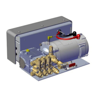
Detailed breakdown and identification of AQUIS 1.5 system components.
Detailed breakdown and identification of AQUIS 3.0 system components.
Detailed breakdown and identification of AQUIS 6.0 system components.
A general diagram illustrating the typical foam system setup.
Explains the function of components in a typical foam system setup.
Important safety and procedural notes before beginning system installation.
Warning against modifying components and its warranty implications.
Provides physical dimensions for AQUIS 1.5, 3.0, and 6.0 models.
Provides physical dimensions for Digital and Manual OITs.
Dimensions for Foam Tee, Foam Manifold, and Check Valves.
Key considerations and guidelines before beginning the foam system installation.
Guidelines for determining pump location and mounting procedures.
Step-by-step instructions for installing the OIT.
Steps for installing the master waterway check valve in-line with the waterway.
Instructions for orienting and installing the foam manifold.
Steps for orienting and installing the flowmeter tee and connecting its cable.
Instructions for connecting supply, injector, and bypass hoses, and fitting specifications.
Instructions and safety warnings for connecting the power supply to the pump.
Procedure for connecting the tank level sensor cable to the terminal strip.
How to install the concentrate inject check valve in the injector fitting.
Steps to calibrate the manual operator interface terminal.
Procedures for entering calibration mode and setting parameters on the digital OIT.
How to adjust the default mix percentage setting (F1) on the OIT.
Procedure for calibrating the water flow rate using the OIT.
How to select the concentrate source (single/dual tank) for the system.
Key safety considerations and warnings for operating the foam system.
Specific warnings about hot surfaces and hot liquid during operation.
Instructions for operating the foam system using the manual OIT.
How to operate the system in normal mode, start/stop pump, and adjust mix ratio.
Detailed steps for operating the foam system in manual mode.
Overview of the digital OIT buttons, display, and LEDs.
How to power up the OIT and interpret the ON LED status.
Starting, stopping, and adjusting foam percentage in manual mode.
Procedures for flushing the foam system using manual mode.
Recommended intervals for performing maintenance procedures.
Steps for checking, draining, and adding oil to the pump.
Procedure for replacing a blown fuse with the correct specification.
Routine cleaning of the wye fitting and strainer.
Lists common symptoms, potential causes, and corrective actions for system issues.
Exploded views and part lists for AQUIS 1.5, 3.0, and 6.0 components.
Exploded views of complete AQUIS units for different models.
Exploded views of AQUIS foam manifold and flowmeter tee.
Various miscellaneous components for AQUIS foam pumps.
Components for optional kits like remote OIT and hose lines.
Details the limited warranty terms, exclusions, and remedies for Waterous products.
| Pump Stages | Single Stage |
|---|---|
| Pump Body Material | Bronze |
| Impeller Material | Bronze |
| Material | Cast Iron, Bronze |
| Connection Type | Flanged |
| Application | Firefighting |