Do you have a question about the Watkiss DigiVAC and is the answer not in the manual?
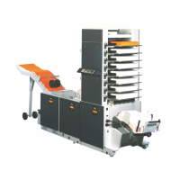
General introduction to the DigiVAC collating system and its capabilities.
Important safety precautions to observe when handling the machine.
Refers to operating instructions in the relevant operating manual.
Defines the viewing perspective for R/H and L/H sides of the machine.
Instructions on how to safely move the DigiVAC unit.
Details the modular system and configuration options for DigiVAC.
Description of the DigiVAC Standard version and its features.
Description of the DigiVAC+ version with GUI and multi-tower capabilities.
Lists and illustrates the various modules that make up the DigiVAC system.
Provides a high-level overview of the DigiVAC system architecture and components.
Details the location, function, and rating of fuses used in the DigiVAC system.
Lists the essential tools recommended for Watkiss engineers to service the DigiVAC.
Lists consumable items required for maintenance and repair of the DigiVAC.
Lists special service aids and diagnostic equipment for the DigiVAC.
Covers common service procedures applicable to the DigiVAC system.
Procedure for entering Bin Test Mode for diagnostics and testing.
Step-by-step instructions for removing the rear conveyor assembly.
Instructions for removing the left-hand side plates for access.
Procedure for addressing bins after installation or PCB replacement.
Procedures related to the Top Module of the DigiVAC.
Instructions for replacing worn or damaged top drum and conveyor belts.
Procedures for servicing the control panel of the DigiVAC Standard.
Step-by-step guide for removing the standard control panel assembly.
Instructions for accessing and using the Engineering Mode on the standard control panel.
Procedures for servicing the Graphical User Interface (GUI) control panel.
Guidelines for cleaning the GUI touch-screen to ensure proper operation.
Procedure for calibrating the GUI touch-screen for accurate input response.
Procedures for servicing the various feeder modules.
Instructions for removing the feeder head assembly.
Procedure for replacing a faulty feeder clutch assembly.
Instructions for replacing a faulty bin emitter or sensor.
Procedure for replacing damaged or broken bin feeder drive belts.
Guidelines for correctly tensioning bin feeder drive belts for optimal performance.
Procedures related to the Base Module of the DigiVAC.
Step-by-step guide for replacing the main drive motor and gearbox.
Instructions for replacing the vacuum pump motor.
Procedure for checking, cleaning, or replacing the main air filter.
Instructions for replacing the SMD 8200 Inverter unit.
Procedures for servicing and maintaining the X-Jogger module.
Guide for adjusting and cleaning X-Jogger sidelay and endlay screws.
Instructions for replacing the X-Jogger control PCB or fuse.
Procedure for adjusting the jogging power of the X-Jogger.
Provides wiring and connection diagrams for the DigiVAC system.
Illustrates the overall block diagram of the DigiVAC system.
High voltage wiring connections for early serial numbers (sheet 1).
Low voltage wiring connections for Standard models (early serial numbers).
Details of the various Printed Circuit Boards (PCBs) used in the DigiVAC.
Information on the X-Jogger Control PCB.
Details of the DigiVAC Base PCB, a key component for system operation.
Information on the SMD 8200 Inverter, used in later Base Modules.
Information on the GUI software, installation, and updates.
Overview of methods for installing new software revisions.
Procedure for updating software using an SFM Memory Card.
Method for updating software via a serial RS232 connection.
Method for updating software using a network Ethernet connection.
Detailed procedure for installing software using RS232.
Detailed procedure for installing software via Ethernet.
Instructions on setting up network connections between DigiVAC units.
Explanation of error codes indicated by audible bleeps.
Checklist for inspecting the DigiVAC after it has been built or reconfigured.
Checklist for inspecting the DigiVAC before it is shipped to the customer.
A schedule outlining routine maintenance tasks for the DigiVAC.
Checks and considerations before installing the DigiVAC.
Procedure for safely unpacking and physically installing the DigiVAC.
Instructions for upgrading an 8-bin DigiVAC system to a 12-bin configuration.
Procedure for upgrading a DigiVAC Standard to a DigiVAC+ with GUI.
Instructions for installing a second tower to create a multi-tower system.
A chart listing common faults and their probable causes and solutions.
Information on identifying and resolving faults related to fuse failures.
Technical specifications for the DigiVAC system.
| Brand | Watkiss |
|---|---|
| Model | DigiVAC |
| Category | Industrial Equipment |
| Language | English |