TI 420 v5 0515 Page 3
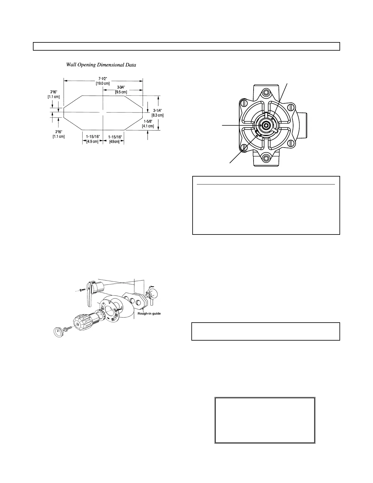
2. Use rough-in guide to position valve 2-3/4"± l/4"
[7.0 cm ± 0.6 cm] from center line of inlets to face of
finished wall (see Dimensional Data section).
3. Facing front of mixer, connect hot water to left side
(marked HOT) and cold water to right side (marked
COLD). Inlet and outlet connections must be piped cor-
rectly for proper operation of valve. Be certain connec-
tions are made exactly as described above. If hot and
cold inlets are reversed, valve will not function properly.
Solder Piping
Excessive heat from soldering can damage the internal
parts of the valve. If you use copper tubing, flare fittings
must be installed within 12" (30.5 cm) of the valve or
triple duty checkstops) to protect the valve. If flared fit-
tings cannot be installed, remove the internal parts of the
valve and checkstops before soldering.
Finish Rough-In
4. After finished wall is complete, remove rough-in guide
to allow installation of the dial handle.
5. Peel off backing of dial gasket and attach it to inside
top edge of dial plate. Allow approximately 1/8" [0.3
cm] of gasket to protrude past dial edge.
6. Install dial and handle and secure with screws provided.
Test the System
Before final assembly, test the system and check the
maximum temperature setting.
7. Verify that the valve is in the OFF position (fully clock-
wise position).
8. Turn on water supply, and then rotate the valve handle
counterclockwise. Water should come through the
spout/showerhead.
Maximum T
emperature Setting/Handle Rotation Stop
The handle rotation setting must be adjusted to limit the
distance the user can rotate the handle towards the full
hot water position.
CAUTION: Any repair or modification of the valve may
affect the high temperature setting. The maximum
temperature setting must be checked by the installer
before use.
9. Remove the valve handle and both splined stops.
10. Adjust the valve to the desired maximum outlet temper-
ature. Install the splined limit stop with its tab against
the bottom of the bonnet stop.
11. Turn the stem clockwise until the water stops. Install
the second splined limit stop with the tab against the
top of the bonnet stop.
12. Replace handle. Repeat steps 8 through 14 until
desired maximum outlet temperature is reached.
Remove handle before final assembly.
CAUTION: Resetting of the splined stop can result in
temperatures higher than 110°F [43°C].
After Rough-In and Testing of System:
Maximum Temperature Setting (Handle Rotation Stop)
CALIFORNIA PROPOSITION 65 WARNING
WARNING: This product contains chemicals
known to the State of California to cause cancer
and birth defects or other reproductive harm.
(California law requires this warning to be given
to customers in the State of California.)
For more information: www.wattsind.com/prop65
INSTALLATION (continued)
 Loading...