Benchmark Platinum-Edge [ii]: Installation Manual
SECTION 2 – INSTALLATION
OMM-136_E • GF-210 • 12/13/2019 Technical Support • (800) 526-0288 • Mon-Fri, 8 am - 5 pm EST Page 37 of 57
NOTE:
To facilitate making the connections, these strip can be lifted off the I/O board. The entire
strip is then remounted on the I/O board after all connections have been made. If a
connector strip is removed, it must be re-mounted in its original orientation (connecting wires
arranged around the outside perimeter of the I/O board).
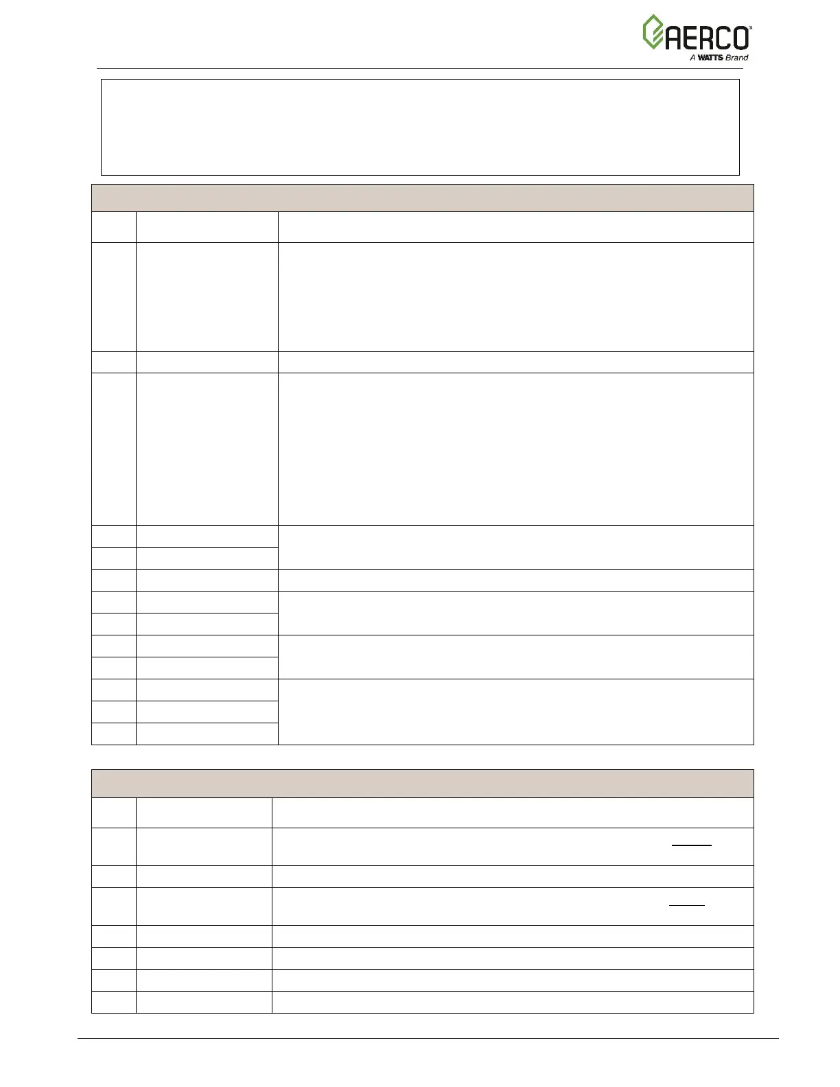
Connector Strip J3 Terminals
Outside Temp +
Outside Temp -
Connections to Outside Air Temperature (OAT) sensor (P/N 61048). Used
on Manager and Backup Manager units. Required for the OUTDOOR
RESET mode of operation. To enable this mode, go to the Controller’s
Main Menu → Advanced Setup → Unit → Application Configuration
and set SH Operating Mode to Outdoor Reset, then configure the related
parameters.
Connection to the shield from any cable.
Supply Header +
Supply Header –
Connection to the Supply Header temperature sensor (2 wire sensor P/N
24410, or 4 wire sensor P/N 61058) for:
• Main Loop (in a Variable-Primary application)
• Secondary Loop (in a Primary-Secondary application)
• Loop 1 (in a Multi-application)
Typically, used on Manager and Backup Manager units.
For more information, refer to the Benchmark Boiler Application Guide
(TAG-0019)
Connection to the Analog Remote Signal, if Operating Mode = Remote
Setpoint. Used on Manager and Backup Manager units.
Connection to the shield from any cable.
Reserved for future use. Boiler Variable Speed Pump. Connection for the
VFD signal to the pump,
Dedicated to internal communication between units in a BST or WHM
system. ACS (legacy) panel should also be connected to this terminal.
Connector Strip J4 Terminals
In a multiple application configuration, connection to the 2
nd
loop supply
header temperature sensor.
Ground connection for Supply Loop 2
In a multiple application environment, connection to the 2
nd
loop return
header temperature sensor.
Connection to the shield from any cable.
Reserved. Spare temp sensor
Ground connection for RTD Spare 1
Reserved. Spare temp sensor

 Loading...


