Benchmark Platinum-Edge [ii]: Installation Manual
SECTION 2 – INSTALLATION
OMM-136_E • GF-210 • 12/13/2019 Technical Support • (800) 526-0288 • Mon-Fri, 8 am - 5 pm EST Page 39 of 57
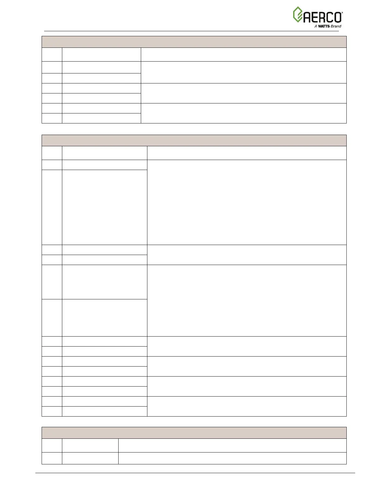
Connector Strip J6 Terminals
Connection to an auxiliary device interlock, such as louver open
feedback or flow sensor.
Connection to an auxiliary device interlock that requires a delay before
the plant starts firing.
Delayed Interlock 1 Return
Connection to an auxiliary device interlock that requires a delay before
the plant starts firing.
Delayed Interlock 2 Return
Connector Strip J7 Terminals
Connection to an auxiliary device enable/disable signal, such as:
• System Pump
• Summer Pump
• Pump 2
• Louver
• Louver 2
• Damper
• Other
To assign/program its function, go to the Controller’s Main Menu →
Advanced Setup → Ancillary Devices → Relays, then set the
Relay to Spare 2 Relay and the Name to one of the above devices.
Connection to a DHW Pump enable/disable signal.
Connection to an auxiliary device enable/disable signal, such as:
• Swing Valve 2
• System Pump
• Summer Pump
• Pump 2
• Louver
• Louver 2
• Damper
• Other
To assign/program its function, go to the Controller’s Main Menu →
Advanced Setup → Ancillary Devices → Relays, then set the
Relay to V2/Spare 1 Relay and the Name to one of the above
devices.
Connection to a reserve/backup boiler enable/disable signal.
Connection to a Swing Valve 1 enable/disable signal.
Connection to a Fault/Remote Alarm enable/disable signal.
Connection to an auxiliary device enable/disable signal.
Connector Strip J14 Terminals
Connection to the building automation system (BAS) network (Modbus RTU,

 Loading...


