EasyManua.ls Logo

wattstopper LMZC-301 User Manual

wattstopper LMZC-301
2 pages
To Next Page IconTo Next Page
Page #1 background imageLoading...
Page #1 background image
Installation Instructions
LMZC-301
DLM Zone Controller
Step 1
Remove the P115/277 board with the LMPI assembly
Step 2
Mount the LMCZ-301, using 4 mounting screws.
Step 3
Reinstall the P115/277 board with the LMPI assembly
Note: If installing an optional LMRC-100s, attach it to the
power supply board before reinstalling. See the instructions
at the bottom of the following page.
Step 4
Connect the incoming power cable to the power supply (and if used,
to the LMRC-100).
Green
(Ground)
White
(Neutral)
Black
(Line)
Black
(Line)
Green
(Ground)
White
(Neutral)
Connect as shown below for 115V Connect as shown below for 277V
SPECIFICATIONS
Input voltage ..................................................115/277V 60 Hz
Class 2 connection to two independent DLM local networks (IRB)
24VDC output, up to 250mA across 2 RJ45 ports per
local network (A and B networks, 250 mA each)
If using an optional LMRC-100 to boost output, the
amount is 400 mA per network (two LMRC-100s
needed if using both networks)
Free-topology DLM local network segments may include
LMFC-011 Fixture Controllers, DLM switches, occupancy
sensors, daylight sensors and input modules
Category 5e cable, up to 1,000 ft. total per local network
Terminals for connection to DLM segment network
(BACnet MS/TP)
Segment network parameters
WattStopper LM-MSTP wire
Linear topology; 4000 ft. maximum per segment
Operating conditions:
for indoor use only ...................... 32-122 F (0 – 50 C)
........................................5-95% RH, non-condensing
UL and cUL listed
Green
(Ground)
White
(Neutral)
Black
(Line)
Green
(Ground)
White
(Neutral)
Black
(Line)
Wiring for an LMRC-100 Wiring for two LMRC-100s
Question and Answer IconNeed help?

Do you have a question about the wattstopper LMZC-301 and is the answer not in the manual?

wattstopper LMZC-301 Specifications

General IconGeneral
ManufacturerWattstopper
TypeController
Product TypeLighting Controller
Frequency60Hz
Load TypeIncandescent, Fluorescent, LED
Operating Temperature0 to 50°C

Summary

Specifications

Input Voltage

Specifies the input voltage and frequency for the device.

Network Connections

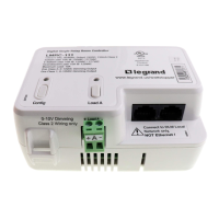
Details Class 2 connections to DLM local networks via RJ45 ports.

Segment Network Parameters

Outlines parameters for DLM segment network wiring, like topology and length.

Operating Conditions

Specifies environmental requirements for indoor use, temperature, and humidity.

Certifications

Indicates the device is UL and cUL listed.

Installation Guide

Step 1: Remove Board Assembly

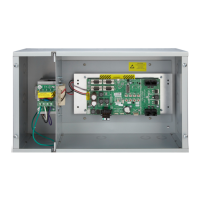
Remove the P115/277 board with the LMPI assembly from the enclosure.

Step 2: Mount Unit

Secure the LMCZ-301 unit into its mounting location using screws.

Step 3: Reinstall Board Assembly

Reinstall the P115/277 board with the LMPI assembly after mounting.

Step 4: Connect Power Cable

Connect the incoming power cable to the power supply and optional LMRC-100.

Step 5: Attach Ground Wire

Connect the ground wire to the appropriate terminal.

Step 6: Connect Power Supply

Connect the power supply unit to the LMPI board.

Step 7: Connect Network Cables

Connect LMRJ cables to RJ45 jacks for DLM network communication.

Optional LMRC-100 Installation

Instructions for installing an optional LMRC-100 to boost network power output.

Warranty Information

Related product manuals