Note 1: “1” dans les deux directions indique une diode ouverte; une lecture
basse indique une diode court-circuitée. Les jonctions de transistors
peuvent être testées comme des diodes.
CONTINUITY TEST
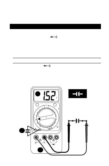
The Continuity test checks electrical continuity between two contact points. ❶
Set the Function/Range switch to . ❷ Plug the black test lead into the
–Rx jack (black) and connect the test lead tip to one of the contact points. ❸
Plug the red test lead into the +Rx jack (red) and connect its test lead point to
the other contact point. (See Figure 1 for connections). ❹ The internal beeper
emits a tone when resistance is less than approx. 100Ω.
D • Durchgangstest
❶
Funktionsschalter auf stellen.
❷
Rotes Meßkabel mit +Rx (rot)
Eingang und schwarzes mit -Rx Eingang verbinden.
❸
Meßspizen mit
Schaltkreis verbinden.
❹
Bei R ≤100Ω wird ein akustische Signal
abgegeben.
– 12 –