8
ThermoConnect
See heater wiring harness.
Check if the power supply is fused with
a 5A fuse.
Connect the red wire (pin9, +) to the
power supply.
In multi-battery systems connect the
wiring harness to the battery that is
connected with the air- or water
heater.
Connect the brown wire (pin1) of the
ThermoConnect wiring harness (
) to
ground.
Connect the plug of the
ThermoConnect wiring harness (B) to
the 16-pin connector on the
ThermoConnect.
Tie up the loose part of the
ThermoConnect wiring harness.
If necessary then update wiring har-
ness of the heater.
■ Always check the wiring diagram
of the heater.
■ When connecting more than one
control element to a heater:
Make sure that the heater and the
control devices are connected via
WBus (Pin2 / yellow wire) .
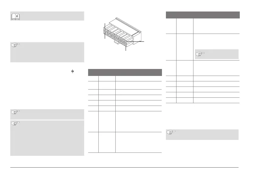
16-pin plug
Fig.11 ThermoConnect 16-pin plug
See also Fig.22
Pin Colour Description
1 Brown Pin 31, ground
2 Orange W-bus
3 Not connected
4 Not connected
5 Not connected
6 Brown Push button
7 Grey
Input 1, (+ 0V...+32V,
min. Impedance 10kΩ,
state up >5V, state
down < 0.5V)
8 Violet
Input 2, (+ 0V...+32V,
min. impedance 10kΩ,
state up > 5V, state
down < 0.5V)
Pin Colour Description
9 Red
Pin 30, supply,
(+9V…+32V, 5A fuse
required)
10 Yellow
Output 1, (0.5A, same
as supply voltage when
controlled)
This is not the W-
bus signal.
11 White
Output 2, (0.5A, same
as supply voltage when
controlled)
12 Green Push button
13 Grey Push button
14 Blue Push button
15 Not connected
16 Not connected
9.3 Heater wiring harness
(Ref. Fig.9)
■ W-bus: connect yellow wire.
■ Analogue heater: connect black wire.
Always check the wiring diagram of
the heater.
10 Vehicle ventilation control
The ThermoConnect can be configured to
control the vehicle ventilation separately.
Connect either Output 1 (Pin 10) or
9
16
8
1