ASSEMBLY
Remove the machine and contents from the carton. Be sure the carton is empty before discarding.
If you require assistance with regards to the contents or operation of the machine, please contact us:
Tel: 01793 333212
Email: customerservice@webbgardenpower.co.uk
Opening hours weekdays: February to October 8:30am - 5:30pm / November to January 8:30am - 5:00pm
(Closed Bank Holidays)
WARNING
Stop the motor, apply the chain brake and remove the electrical plug from the mains prior to carrying out
repairs or maintenance operations.
DO NOT attempt to start this machine without it first being FULLY assembled.
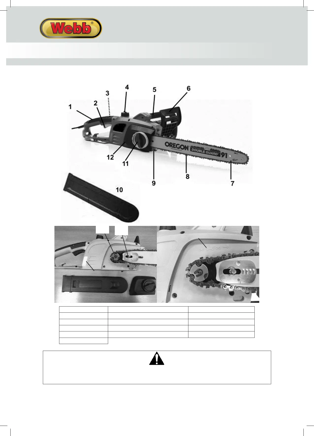
CHAIN & BAR ASSEMBLY
1. Place the chainsaw on a flat, solid surface.
2. Slide the chain in the groove of the guide bar.
3. Ensure the chain is in the correct running direction.
4. Ensure the chain tensioning catch on the guide bar is facing outwards.
5. Fit the chain onto the drive sprocket and guide bar, so the fastening bolt and two guide fins fit into the
keyway of the guide bar.
6. Ensure all parts are seated correctly & hold the chain and guide bar in a level position.
7. Pull the guide bar to the right, ensuring the chain is tight and positioned in the guide bar groove.
8. Fit the cover plate; ensure the chain catcher fits into the groove of the cover plate.
9. Press the cover plate firmly onto the machine and screw on the cover plate, with the locking knob.
 Loading...