PRINCIPAL OF OPERATION
All models of the Webster
®
Hardness Tester
operate in the same manner. The material to be
tested is placed between the anvil and the pen-
etrator. Pressure is applied to the handles until
“bottom” is felt at which time the dial indicator is
read. Excess handle pressure beyond this point
is not harmful but is unnecessary.
The Tester should be held still while taking the
reading as any twisting or other movement
during testing will result in untrue readings as
experienced with any other hardness testing
machine.
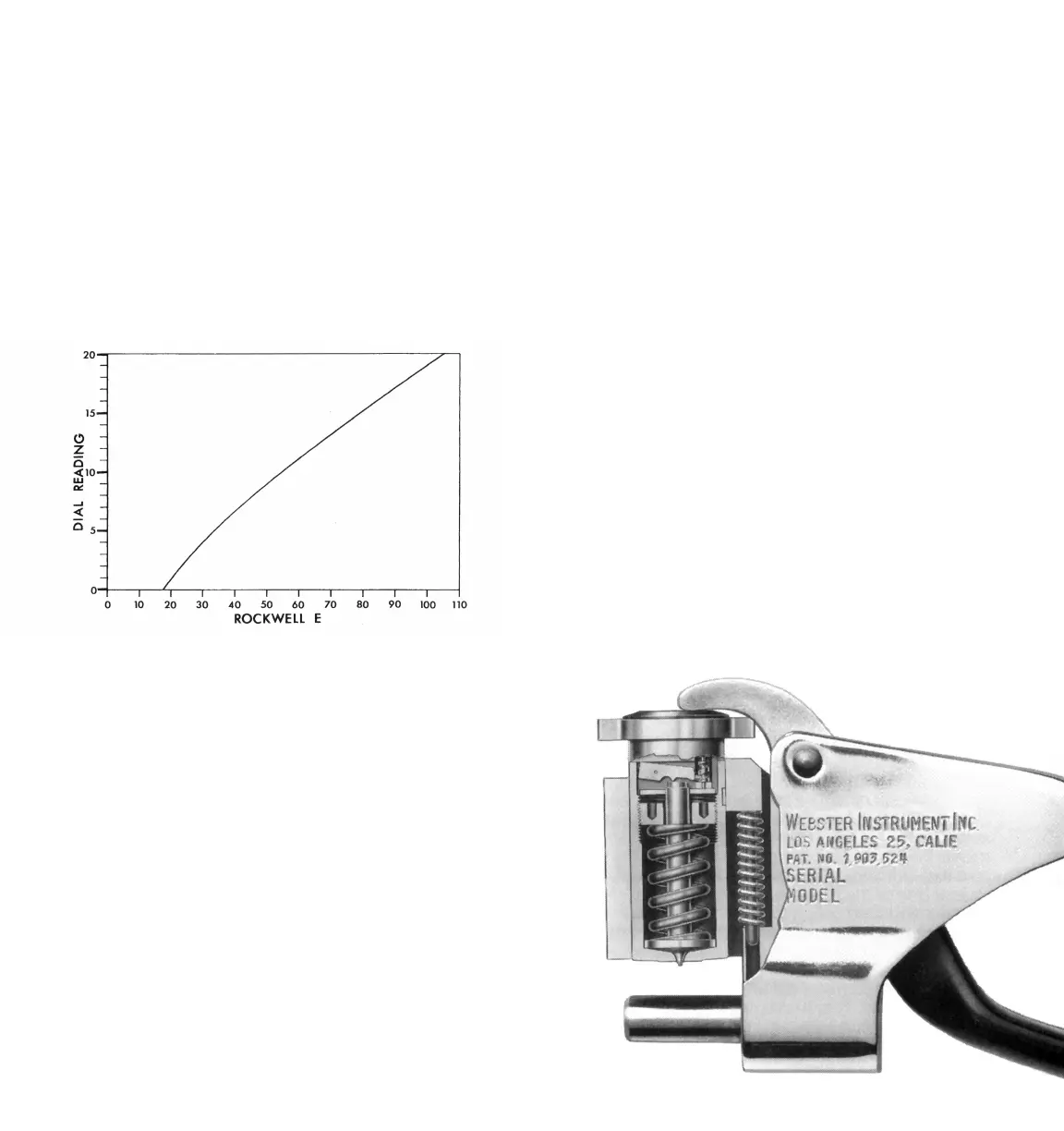
By reference to cutaway view Fig. 1 it will be
seen that the principal working parts are con-
tained in the penetrator assembly. The pene-
trator assembly consists of the penetrator, load
spring, adjusting nut, penetrator housing, hous-
ing key, return spring and dial indicator. This
entire assembly moves toward the anvil as a unit
when pressure is applied to the handles.
As handle pressure is applied and the penetra-
tor assembly moves toward the material, the
penetrator point makes contact rst because
it projects beyond the at face of the housing.
Continued
Fig. 1
SPECIAL INSTRUCTIONS FOR THE
WEBSTER
®
MODEL BB-75 TESTER
The Model BB-75 Tester is a combination of the
Model B-75 penetrator and the Model B load
spring. This combination provides slightly more
sensitivity on the softer materials than the B and
B-75. The Model BB-75 was developed to answer
the need of certain industries for rapidly testing the
hardness of electro-deposited copper and copper
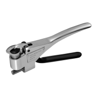
in the low hardness range. When adjusted prop-
erly the readings obtained on copper samples are
approximately as shown in chart Fig. 8.
FIG. 8 Hardness Range, Copper-Model BB-75
REPAIR AND REPLACEMENT
Cutaway view Fig. 9 clearly shows the working
parts of the various testers. Each tester has a seri-
al number stamped on the frame and this number
should be mentioned in all correspondence rela-
tive to repair. The model designation is stamped
before the serial number and this designation
must be observed when ordering parts or making
repairs.
Penetrators should be examined periodically for
wear with a magnifying glass. Penetrators showing
appreciable wear should be replaced with new
ones.
For purpose of clarication the following few points
are added:
The penetrator housings for all models are identical. The
dial indicators for all models are identical. All models em-
ploy single point penetrators but are different in contour
and should never be used inter-changeably. The load
springs for Models B and BB-75 are identical. The Model
B-75 uses a heavier spring. Return springs for all models
are identical.
310
 Loading...