Continued handle pressure causes the penetrator
to recede into the housing against the load of the
load spring.
“Bottom” is felt when the at lower end or face of
the housing rests against the material at which
point further pressure on the handles simply
squeezes the metal between the housing face and
the anvil. At this point the only load on the penetra-
tor is that of the load spring which is governed by
the setting of the load spring adjusting nut.
The dial indicator is tted to the upper end of
the penetrator housing and is actuated by the
movement of the penetrator. On metal of extreme
hardness the penetrator will recede into the hous-
ing until the tip is ush with the housing face. This
is the position of maximum penetrator travel and
is used for “zero” or full scale setting of the dial
indicator. It is obtained by completely compressing
the penetrator against the bare anvil. This will be
explained in detail later (see zero adjustment
page 5).
On metal of extreme softness the penetrator will
not recede into the housing at all, there will be no
movement of the penetrator and no reading will be
obtained on the dial indicator.
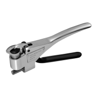
ZERO AND LOAD SPRING ADJUSTMENTS
There are only two adjustments on the Webster
®
Hardness Tester regardless of model; the zero
adjustment of the dial indicator and the load spring
adjustment. The zero adjust screw atop the dial
indicator case shown in Fig. 2 is adjusted at the
factory to take care of the accumulated toleranc-
es of a particular penetrator, housing and dial
indicator. It need never be adjusted unless one of
the reasons shown on page 5 is present and then
only if the indicating hand does not reach full scale
when the tester is operated against its bare anvil.
Care must be exercised in making the adjustment
in that the screw should not be turned until after
the handles are depressed fully. This prevents the
possibility of the indicating hand passing full scale,
striking the case and applying high torque to the
internal mechanism of the indicator.
Graduations are 1 to 20. Hardness readings
obtained with the Model B-75 can be compared to
other standard hardness readings such as Rock-
well, etc.
As in all models the amount of load on the pen-
etrator is determined solely by the load spring
adjustment and is not affected by excess handle
pressure.
The Model B-75 uses a slightly heavier load spring
than the Models B and BB-75 but requires very
little additional pressure on the handles to operate.
The B-75 Tester is designed for use on brass and
mild steel and the 20 dial graduations will cover
the hardness range from annealed to full hard
brass. The B-75 Tester is more sensitive than the
Model B and therefore covers a smaller range of
hardness.
Each B-75 Tester is accompanied by a standard
sample stamped with the proper dial indicator
reading. This sample is to be used for routine
check to insure proper load spring adjustment.
Before making this check be sure the dial indicator
is in proper zero adjustment. (See par. 2, page 5)
If the reading taken on the standard sample does
not agree with the number stamped on it, load
spring adjustment must be changed to make the
readings agree.
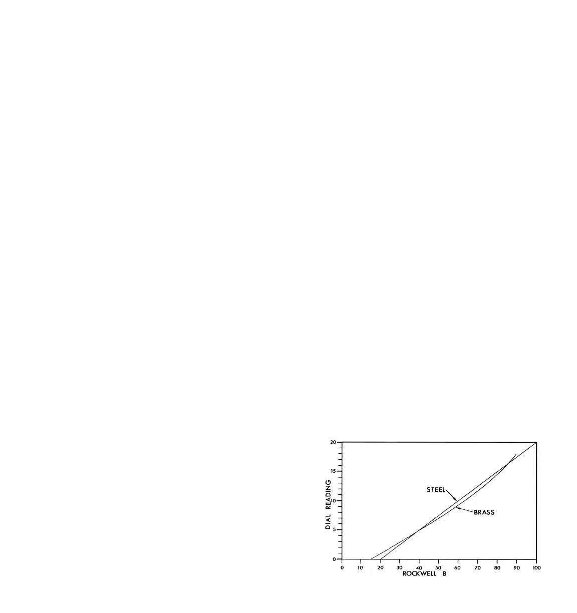
With proper zero and load spring adjustment,
readings obtained on brass and mild steel samples
are approximately as shown in chart Fig. 7.
FIG. 7 Hardness Range, Brass--Model B-75
94
 Loading...