THE ZERO ADJUSTMENT
The method of making the zero adjustment of the
dial indicator is shown in Fig. 2.
With the tester operated against the bare anvil,
and handle pressure maintained, the zero adjust-
ing screw is slowly turned until the hand of the dial
indicator rests on the zero line of the dial face, which
is full scale reading. This zero line is at 20 on the B,
B-75 and BB-75 models. After this zero adjustment
has been properly made it should never be changed
except for one of the reasons listed below:
1. When a new penetrator is installed.
2. When the dial indicator is changed from one
penetrator to another.
3. When excessive wear has resulted in need for
a slight adjustment.
The operator can instantly check for correct zero
adjustment by operating against the bare anvil and
noting whether the hand comes to rest on the zero
line.
The zero adjustment should never be changed for
any other reason and it is extremely important that
the operator be warned of this fact. Never use the
zero adjustment to make the tester read correctly on
the sample but adjust the load spring, as described
below.
LOAD SPRING ADJUSTMENT
The load spring adjustment is the same for all mod-
els. The special wrench provided with each tester
is used as shown in Fig. 3 to vary the load on the
penetrator by applying more or less pressure on the
load spring. This is accomplished by rotating the
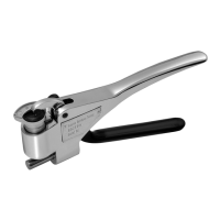
Fig 2 Zero adjustment screw ‘A” is indicated by arrow
SPECIAL INSTRUCTIONS FOR THE
WEBSTER
®
MODEL B-75 TESTER
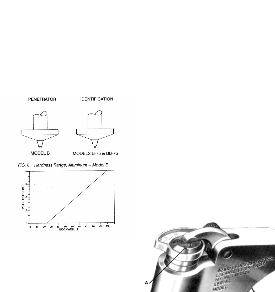
The Model B-75 Tester has a single point pene-
trator with a different contour from the Model B
which can be identied from Fig. 5. The same dial
indicator is used for the B and B-75 Testers.
Each Model B Tester is accompanied by a stan-
dard sample stamped with the proper dial indica-
tor reading. This sample is to be used for routine
check to insure proper load spring adjustment.
Before making such check the dial indicator must
be in proper zero adjustment (see par. 2, page 5).
If the reading on the dial indicator does not agree
with the number stamped on the stand-ard sam-
ple, slight change must be made in load spring
adjustment until readings agree. When adjusted
properly the readings obtained on aluminum sam-
ples are approximately as shown in chart Fig. 6.
Fig. 5
58
 Loading...