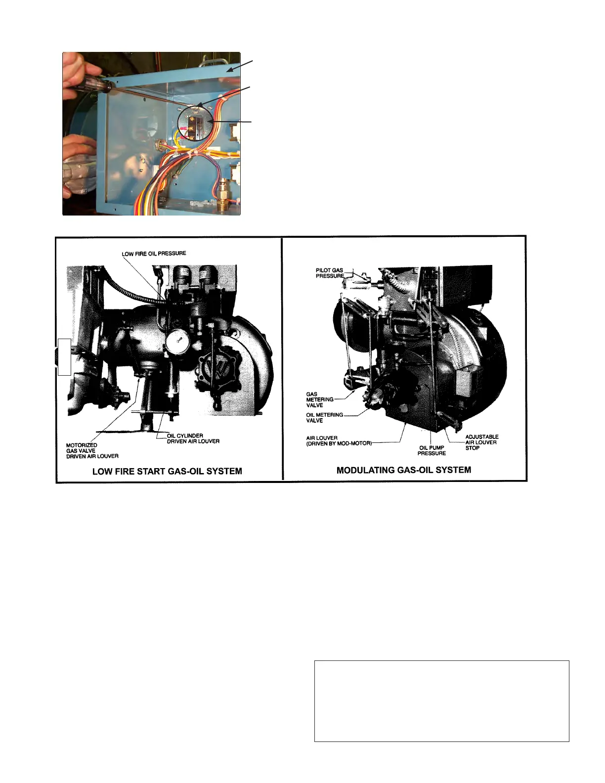
COMBUSTION AIR CONTROL
Panel
Adjusting
Screw
Air Proving
Switch
AIR FLOW INTERLOCKING SWITCH
2. AIR PROVING SWITCH
The air proving switch has been adjusted at the factory
for an initial setting. If the switch trips during initial start-
up, turn the adjustment screw ccw two full turns to re-
duce the trip pressure setting.
3. TYPICAL AIR AND FUEL ADJUSTMENT LOCATIONS
4. Fuel Cam Adjustments (if applicable)
The fuel cam needs to be checked for correct travel
and alignment. Positions can change during shipment
and installation and they must be reviewed prior to
startup. The fuel cams are mounted to the ends of the
jackshaft assembly. A cam follower link follows the profi le
established by the adjusting screws and drives the fuel
valve. A thin metal band is used between the screw and
cam follower to provide a smooth profi le. The adjusting
screws are backed by compressed nylon inserts, which
provide a resistance to turning.
The cam (Figure G-3) should be checked for the following
conditions:
a. At the low fi re position, the roller should be between
the fi rst two adjusting screws. If not, adjust the position
of the cam accordingly, making sure to maintain the same
low fi re fuel valve position.
b. When the linkage is modulated from low to high fi re,
the roller must stay in the center of the adjusting screws
within 1/8”. If needed, the two cam set screws can be
loosened and the cam moved to center it on the roller.
c. At high fi re, the roller should be between the last two
adjusting screws.
d. The adjusting screws should form a smooth contour
with no jumps between the screws.
e. In preparation of startup, the retention plate can
be removed temporarily to make it easier to adjust the
screws.
THE RETENTION PLATE MUST BE REPLACED WHEN
SETUP IS COMPLETE.
If the unit is equipped with a parallel positioning system
(linkageless), the control valves can be positioned and
operated in a similar manner, but accomplished through
the controller. Refer to the instruction manual for details.
CAUTION
LINKAGE AND ACTUATOR MOUNTINGS CAN BE BENT
OR MOVED DURING SHIPMENT AND INSTALLATION.
THEY MUST BE CHECKED PRIOR TO OPERATION AND
ANY FAULTS CORRECTED. FAILURE TO CORRECT A
MISALIGNED CONTROL WILL RESULT IN PREMATURE
FAILURE.
Page 29 Initial Settings
JB Manual